3-3
TMS800E SERVICE MANUAL ELECTRIC SYSTEM
Published 01-29-2014, Control # 496-00
6613-1
3
2
1
4
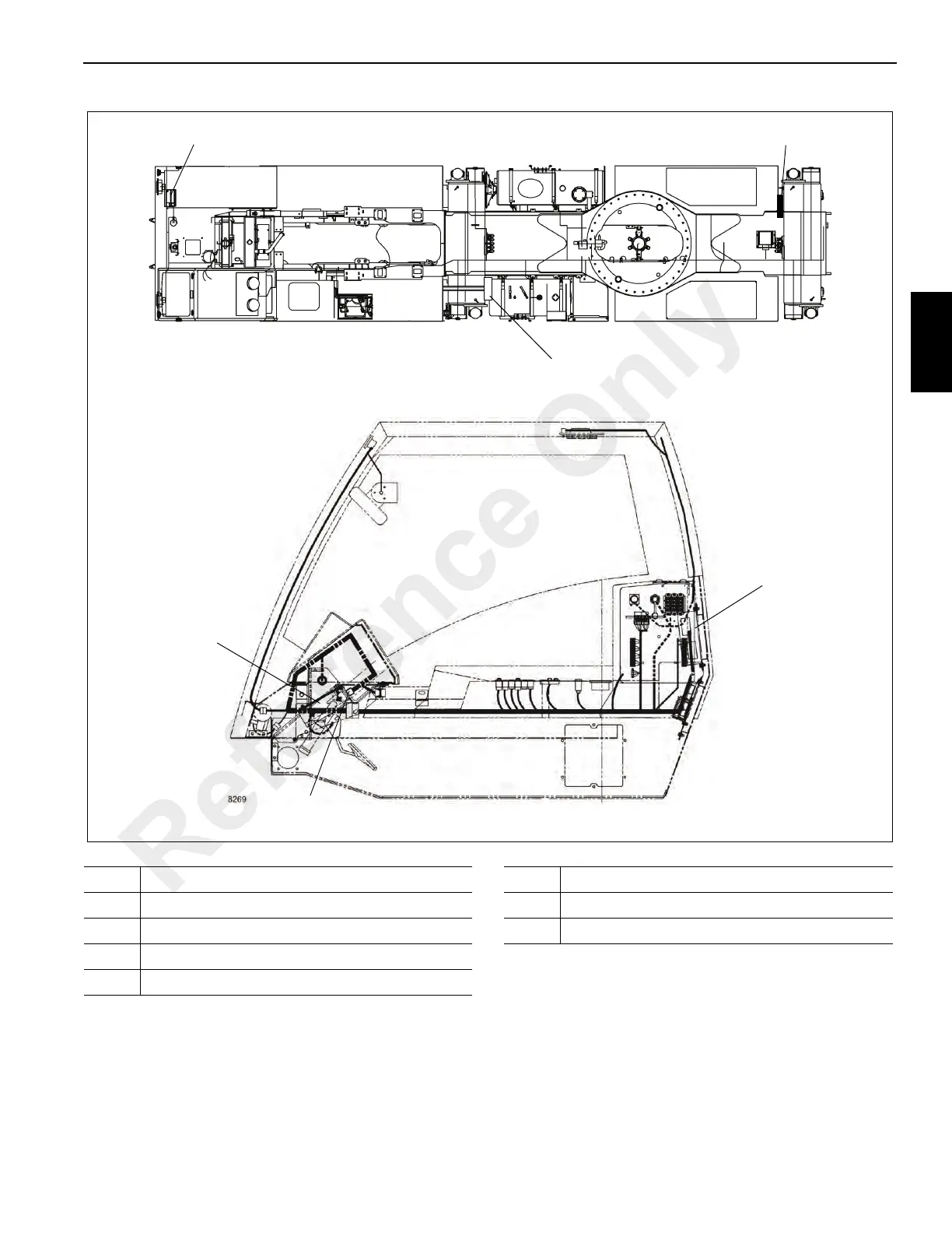
FIGURE 3-1
Carrier Cab
5
6
Item Description
1 Carrier Frame Center Module
2 Carrier Frame Rear Module
3 Carrier Cab Console Module
4 Master Control Module
Item Description
5 Carrier Frame Front Module
6 Engine Diagnostic Connector
Reference Only
 Loading...


