7-31
TMS800E SERVICE MANUAL POWER TRAIN
Published 01-29-2014, Control # 496-00
8. Remove the four cap screws, nuts and washers (3,
Figure 7-17) securing the clutch mounting bracket (4) to
the frame.
9. Attach a suitable lifting device to the PTO clutch/
mounting bracket/pump assembly—the clutch/mounting
bracket/pump weighs approximately 215 kg (474 lb).
10. Remove the assembly and place on a suitable
workbench.
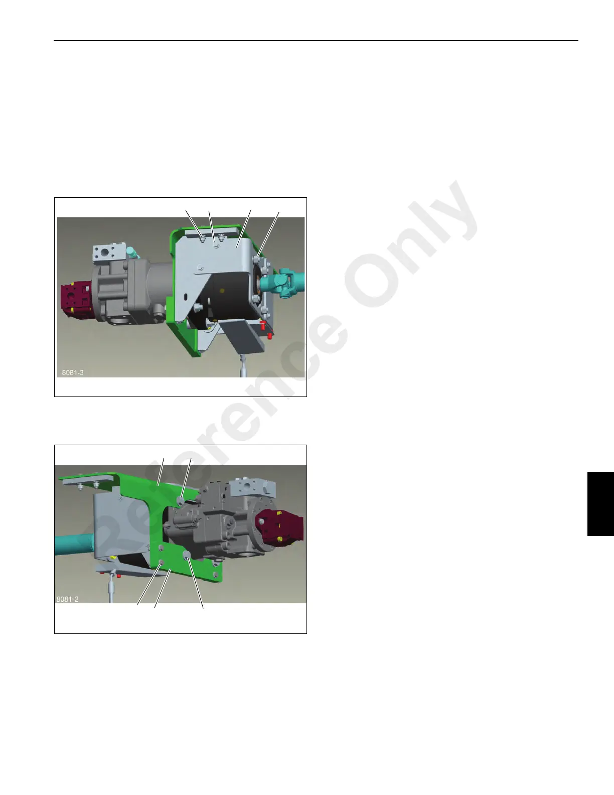
Disassembly
1. Remove the cap screws and washers (1, Figure 7-19)
and double-nut plate securing the front support plate (2)
to the mounting bracket.
2. Remove the cap screws, nuts and washers (1,
Figure 7-20) that fastens the clutch, mounting bracket
and pump together. A bushing (2), on the lower left bolt,
will fall out when the hardware is removed.
3. Remove the three cap screws, nuts and washers (3) that
secure the mounting plate (4) to the mounting bracket
(5).
4. Slide the clutch/front support plate off the pump spline.
5. Using a short Allen wrench or a tool, made by locking
nuts on a 7/16 bolt, inserted into the socket head cap
screws, and held with a wrench, remove the socket head
cap screws, nuts and washers (3, Figure 7-19) that
secures the front support plate to the clutch.
Assembly
1. Assemble bottom plate (4, Figure 7-20) to mounting
bracket (5) around the pump body using the three bolts,
washers, and nuts (3).
2. Slide the clutch onto the pump spline, install the bushing
(2) removed in step 1 above and fasten the assembly
together with the cap screws, nuts and washers (1,
Figure 7-20). Torque hardware, refer to Fasteners and
Torque Values, page 1-13.
3. Loosely attach the front support plate (2, Figure 7-19) to
the front of the clutch using the nuts, washers and
socket head cap screws (3). Secure the front support
plate to the mounting bracket with the cap screws,
washers and double-nut plate (1). Gently tighten
hardware allowing assembly to settle into place. Torque
all hardware according to Fasteners and Torque Values,
page 1-13.
Installation
1. Using the lifting device place the clutch/mounting
bracket/pump assembly onto the crane and loosely
assemble with the cap screws, nuts and washers (4,
Figure 7-19).
2. Connect the hydraulic hoses and air line to the clutch as
tagged during removal. To prime the pumps, add
hydraulic oil to the pumps and hoses before installation.
3. Attach the access cover (1, Figure 7-18) to the front
support plate/clutch/mounting bracket with four cap
screws and washers (2) and two double-nut plates.
Torque all hardware, refer to Fasteners and Torque
Values, page 1-13.
4. Install the driveline onto the clutch input shaft and
transmission output. Secure the driveline to the
transmission with the cap screws, nuts and washers.
Torque hardware, refer to Fasteners and Torque Values,
page 1-13.
5. Adjust the clutch/mounting bracket/pump assembly fore
and aft to position the driveshaft between 6 to 14 mm
(0.24 to 0.55 in) from the clutch face (Figure 7-21).
Reference Only
 Loading...


