8-7
TMS800E SERVICE MANUAL UNDERCARRIAGE
Published 01-29-2014, Control # 496-00
measurements to the first front axle. If the diagonal
distance from one side to the other is not within 6.35 mm
(0.25 in), check the location of the suspension hangers
and air bag hangers and adjust as necessary.
Air Ride Adjustment
NOTE: This model is equipped with an air ride front and
rear suspension. It is necessary to periodically
inspect the suspension for proper adjustment.
Operating this machine with incorrect ride height
adjustments could result in poor ride quality or
possible damage to suspension and axle
components.
1. Front Axle Ride Height - 298 mm (11.75 In) (Figure 8-3)
2.
Rear Ax
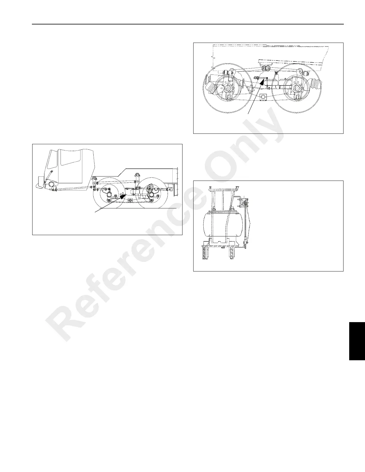
le Ride Height - 387 mm (15.25 In) (Figure 8-4)
3. Adjust rod to achieve proper ride height setting
(Figure 8-5) and torque P-clamp on P-boot to 1.13 to 1.7
Nm (10 - 15 in lbs).
NOTE: Over-tightening of the P-clamp will cut through the
P-boot.
FIGURE 8-3
11.75
Adjust height control valve actuator in horizontal position
with R.H. and L.H. saddle at 298 mm (11.75 in) dimension.
Adjust height control valve actuator in horizontal position
with R.H. and L.H. saddle at 387 mm (15.25in) dimension.
FIGURE 8-5
Do not overtighten nylock nut - rod and arm
should pivot freely
Do not tighten until final adjustments
Do not overtighten P-clamp
Reference Only
 Loading...


