8-30
Published 01-29-2014, Control # 496-00
UNDERCARRIAGE TMS800E SERVICE MANUAL
3. Position the diaphragm over the push rod (see
Figure 8-30).
4. Push the lower cover assembly into the spring brake
chamber and secure with the clamp.
Rear Brake Shoe Removal
1. Remove the anchor pin snap ring, washer, retainer, felts,
seals or capscrews as required.
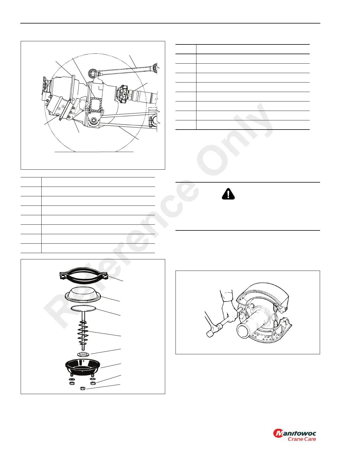
2. Use a brass drift to remove the top anchor pin
(Figure 8-31).
3. Rotate the top shoe to release the tension on the brake
shoe return spring. Remove the shoe (Figure 8-32).
Item Description
1 Brake Air Chamber
2 Axle No. 3
3 Torque Rod
4 Drive Shaft
5 Stabilizer Beam
6 Differential
7 Mounting Bracket
Item Description
1Clamp
2 Diaphragm
3Push Rod
4Spring
5 Shield
6 Cover
7 Mounting Nut
8Jam Nut
CAUTION
Use a brass or synthetic mallet for assembly and
disassembly procedures. Do not hit steel parts with a steel
hammer. Pieces of a part can break off. Serious personal
injury and damage to components can result.
Reference Only
 Loading...


