8-45
TMS800E SERVICE MANUAL UNDERCARRIAGE
Published 01-29-2014, Control # 496-00
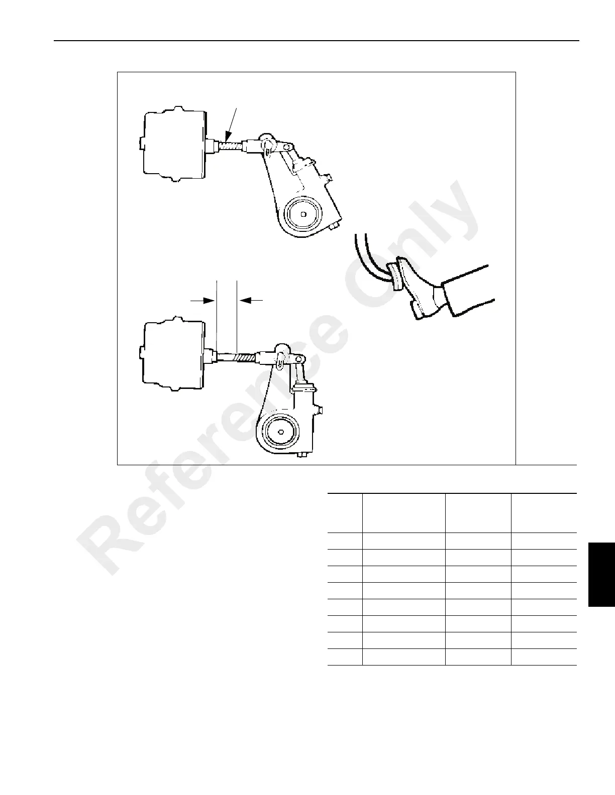
4. Measure the push rod travel or adjusted chamber stroke
from where the push rod exits the brake chamber to the
mark on the push rod. Measure and record the distance
Figure 8-64 step 3.
5. Subtract the measurement recorded in step 3 from the
measurement recorded in step 4. The difference is the
push rod travel or adjusted chamber stroke.
6. Refer to Table 8-3 or Table 8-4 to verify that the stroke
length is correct for the size and type of air chambers on
the vehicle.
If push rod travel is greater than the maximum stroke shown
in Table 8-3 or Table 8-4, inspect the slack adjuster and
replace it if necessary.
7822
FIGURE 8-64
Mark push rod here
to measure stroke.
Step 2
Spring brakes released.
Service brakes not applied.
Spring brakes
released.
Service brakes
applied.
S
t
e
p
1
Step 3
Stroke
6.2-6.9 bar (90-100 psi) in air
tank- engine off
Table 8-3 Standard-Stroke Clamp- Type Brake
Chamber Data
Type
Outside
Diameter (in)
Brake
Adjustment
Limits (in)
Brake
Adjustment
Limits (mm)
6 4 1/2 1 1/4 31.75
9 5 1/4 1 3/8 34.93
12 5 4/16 1 3/8 34.93
16 6 3/8 1 3/4 1 3/4
20 6 25/32 1 3/4 44.45
24 7 7/32 1 3/4 44.45
30 8 3/32 2 50.8
36 9 2 1/4 57.15
Reference Only
 Loading...


