8-51
TMS800E SERVICE MANUAL UNDERCARRIAGE
Published 01-29-2014, Control # 496-00
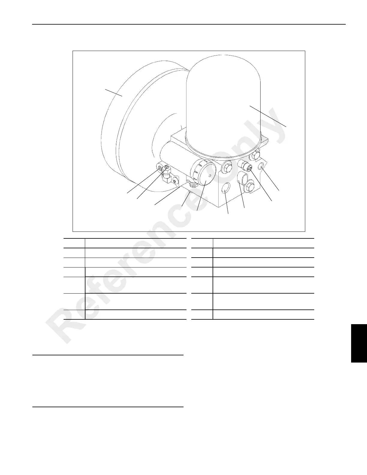
Air Dryer
The purpose of the air dryer is to collect and remove solid,
liquid, and vapor contaminates from the air system. Clean
dry air increases the life of the air system and reduces cost.
The dryer with integral governor (Figure 8-68) consists of a
spin-on desiccant cartridge to collect and remove air system
contaminants before they enter the brake system. The base
contains a check valve, safety valve, heater and thermostat
assembly, four pressure protection valves, threaded air
connections and the purge valve assembly. The purge valve
housing contains the purge valve and turbo charger cutoff.
The turbo charger cutoff prevents loss of engine “turbo”
boost pressure during the purge cycle of the air dryer.
Reservoirs
Four air reservoirs store compressed air for braking and
auxiliary air devices. The first reservoir in the system (in air
dryer module) also acts as a purge tank to remove additional
moisture not removed by the air dryer. The reservoirs have
manual drain valves.
12
11
3
2
4, 5
9
1
8
6
10
7
FIGURE 8-68
Item Description Item Description
1 Governor 7 Auxiliary Delivery Port (Air Out)
2 Unloader Control Valve 8 Inlet Port (Supply From Compressor)
3 Common Reservoir Pressure 9 Pressure Protection Valves
4
Delivery Port Out (To Primary
Reservoir) (Not Shown)
10 Safety Valve
5
Delivery Port Out (To Secondary
Reservoir) (Not Shown)
11 Desiccant Cartridge
6 Heater/Thermostat Connection 12 Purge Reservoir
CAUTION
Do not attempt to adjust or service the pressure
protection valves!
Incorrect pressure protection valve settings can result in
automatic application of vehicle spring brakes without
prior warning.
Reference Only
 Loading...


