WRS – Installation Manual
RECEIVER WITH INTEGRATED INTERFACE (WRI)
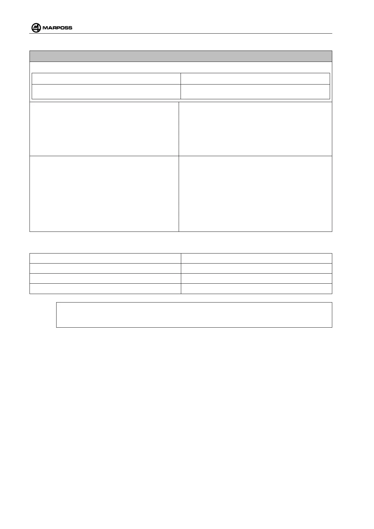
Visual indicators
LED Probe state, battery state and transmitter error.
Display
Displays channels, sub-channels, battery level,
signal level and receiver data programming
Output signals
• Isolated SSR in sink or source configuration
• May be programmed as N.O. or N.C.
• Maximum voltage 30 V.
• Nominal current 40 mA.
• Short circuit protected.
• “State” or “Pulse” logic outputs.
• “Pulse” output with nominal duration of 40 ms.
Input signals
• Opto-isolated in sink or source configuration
• Low current consumption inputs (nominal 1 mA at
15 V)
• Maximum voltage 30 V.
• “State” or “Pulse” START cycle logic input
• Minimum pulse duration 40 ms.
• Selection inputs up to 4 probes via SEL0 and
SEL1
•
Minimum set-up time 5 ms and minimum hold
time 5 ms with respect to the START signal.
Ambient conditions:
Ambient working temperature + 5°÷ + 55°C
Working temperature variation 2°C/h
Relative humidity 90% Max
Ambient storage temperature 0°÷ + 60°C
N.B. (*) :
IP Rating as defined in IEC-60529 and EN-60529.