WRS – Installation Manual
WRI receiver and WRP transmitter, potentially causing the ACS system to intervene (see par. 4.10.11). It is
also possible that the connection remains active due to the movements of the magazine, since each time the
stylus is bent due to a fast movement, or similar action, could reactivate the timeout, resulting in increased
drain on the batteries.
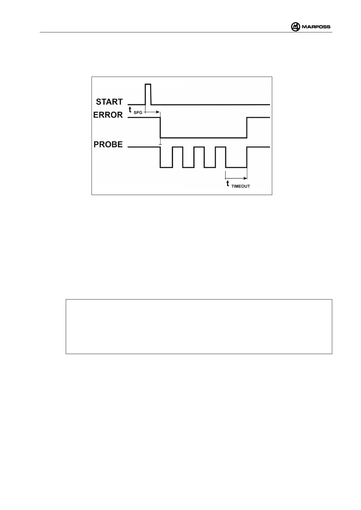
Figure 4-48. Example showing cycle measurement with START in Pulse mode and Touch Retrigger option.
4.12.5 Multiple probe management (Multiprobe)
The two input signals SEL0 and SEL1 can be used to select one of the four transmitters that can be paired
with the WRI receiver. This multiprobe management function can be disabled. The configurations are
described in Table 4-10 and Table 4-11
The minimum set-up time that must be respected between the SEL0 and SEL1 signals and the START
signal is 5 ms.
The minimum hold time that must be respected between the SEL0 and SEL1 signals and the START signal
is 5 ms.
[
N.B.:
If the Multiprobe function is deactivated, it is only possible to pair one WRP transmitter with any
given WRI receiver, irrespective of the selected sub-
channel and how the SEL0 and SEL1 inputs
have been connected. In order to pair additional WRP transmitters, it is necessary to enable the
Multiprobe function and wire SEL0 and SEL1 accordingly.
It is not possible to deactivate the Multi
probe function unless all the paired WRP transmitters but
one have been removed.
4.12.6 Probe 1/Probe 2 outputs
These two outputs indicate the state of the probe and may be programmed independently. An active output
indicated that the stylus is deflected, whereas an inactive output indicates that the stylus is at rest. The
output polarity may be switched between normally open (NO) and normally closed (NC). The signal state
is replicated by the green LED on the WRI receiver panel, irrespective of the polarity:
• Output active: Green LED ON
• Output inactive: Green LED OFF
The logic output may be modified as follows:
 Loading...