WRS – Installation Manual
4.9 Description of the LEDs of the WRP - WRTS transmitter
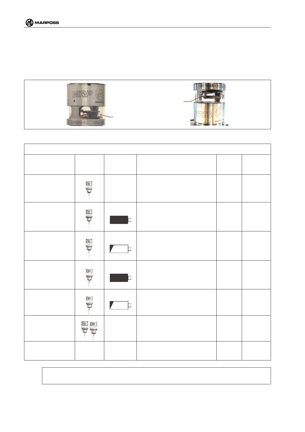
The transmitter WRP - WRTS has 3 pairs of LEDs (Red, Yellow and Green), offset by 180°, that give the
information about the state of the transmitter itself. When the transmitter is activated the signaling LED emits
a flash every two seconds supplying the state information. The LED indicates the states of probe, battery and
transmission:
Figure 4-22. WRP - WRTS transmitter Led
Table 4-6. Indications of the LEDs of the WRP – WRTS. System status
STATE STYLUS BATTERIES LEDs
Flash
duration
LED
lighting
period
Low consumption
At home
- Not lit - -
Active –
in measurement
At home
Charged
1 Green flash 100ms 2s
Active –
in measurement
At home
Low
1 Green flash and 1 Red one in a
rapid sequence
100ms 2s
Active –
In measurement
Bent
Charged
1 Yellow flash 100ms 2s
Active –
In measurement
Low
1 Yellow flash and 1 Red flash in
a rapid sequence
100 ms 2 s
Programming/Pairin
g
- 1 Red flash 100 ms 2 s
Active – In
measurement
1)
Home to
1 Red flash followed by the
measurement status with bent
100 ms 2 s
1)
N.B.:
Applicable only in the case of T25P. See Table 4-7.