WRS – Installation Manual
4.10.8 Aligning the WRP transmitter
The WRP transmitter radiation diagram is practically circular in a plane lying perpendicular to the transmitter
axis. The intensity of radiation is at its maximum level in this plane. Although the system will function
correctly when using reflected transmission paths, it is preferable to use the transmission direction illustrated
in Figure 4-35 when defining how the system will be installed in the machine. When designing the
application, use the 90° extension for the probes in order to optimise the alignment.
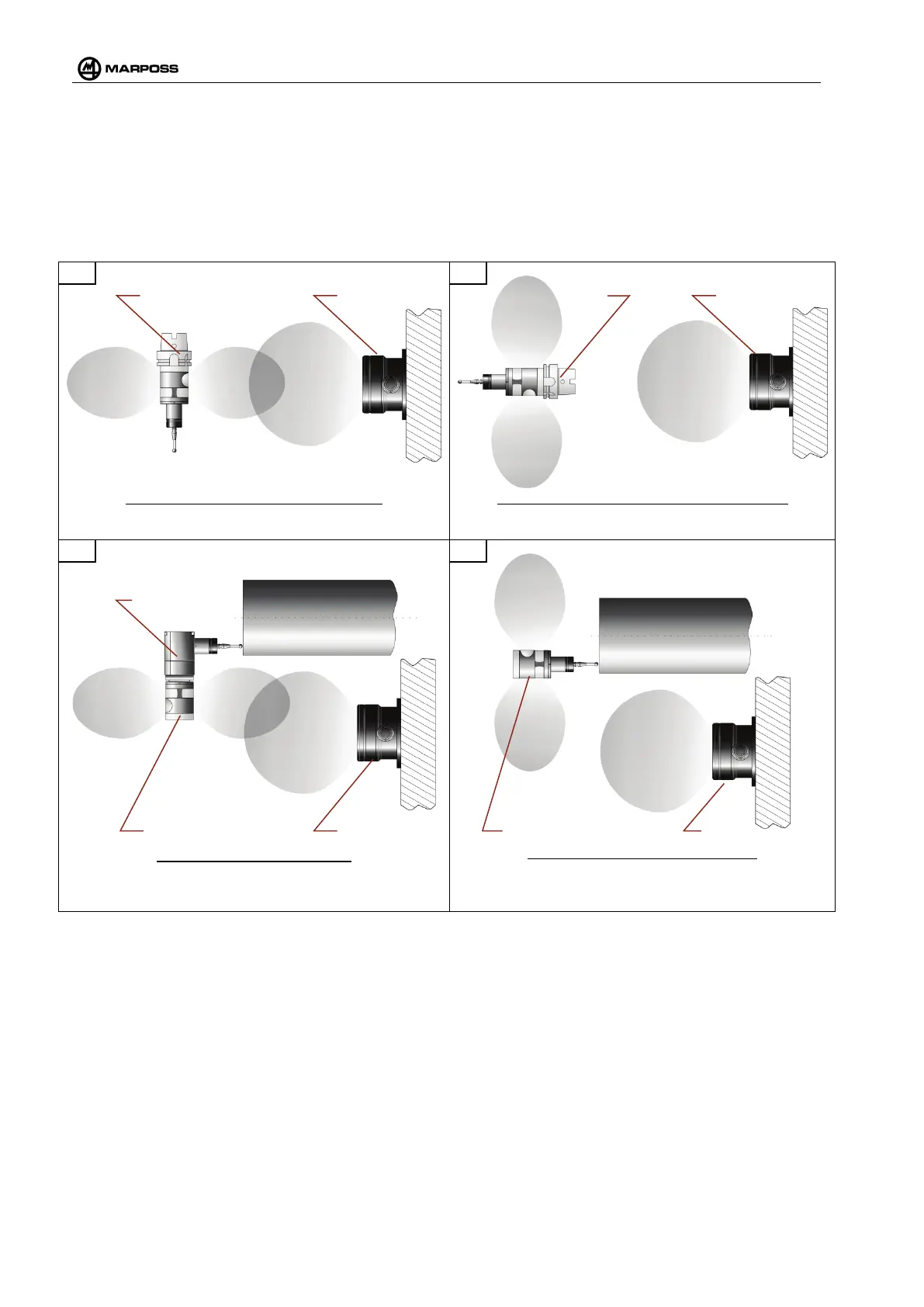
Milling machine: Recommended solution
The predominant radiation directions of the WRP transmitter
and the WRI receiver coincide.
Milling machine: NON Recommended solution
The predominant radiation directions of the WRP
transmitter and the WRI receiver DO NOT coincide.
Lathe: Recommended solution
The predominant radiation directions between the WRP
transmitter and the WRI receiv
er coincide thanks to the
optional 90° support.
Lathe: NON Recommended solution
The predominant
radiation directions of the WRP
transmitter and the WRI receiver DO NOT coincide.
Figure 4-35. Recommended and non recommended WRP transmitter and WRI receiver installation
arrangements.
It is also important to reduce the number of metal objects in the vicinity of the WRP transmitter to a minimum,
since these could affect the performance of the antenna. Also, while the system is operating, it is important to
maintain the WRI receiver and WRP transmitter free from chips and liquid coolant, since both materials are
electrically conductive and may result in significant attenuation of the radio signal.
WRI
WRP WRI WRP