WRS – Installation Manual
4.10.5 Examples showing correct and incorrect ways of positioning the WRI
receiver
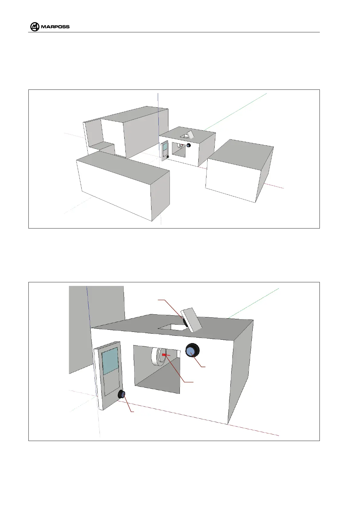
Figure 4-27 shows a schematization of the typical work environment of a machine tool. Use this
schematization to understand how to fit one or more WRS systems optimally.
Figure 4-27. Work environment.
Figure 4-28 shows three typical ways of positioning WRI Receivers:
• WRI 1 – With emission direction on the transmitter.
• WRI 2 – With emission direction parallel to the input direction of the machine window.
• WRI 3 – With emission direction perpendicular to the input direction of the machine window.
Figure 4-28. Positioning of the WRI Receiver.
 Loading...