WRS – Installation Manual
4.4 Aligning and fitting the WRP45 transmitter on the taper shank
ATTENTION
The taper shanks used for the WRP45
transmitter are not compatible with the WRP60
transmitter.
Here there is described the procedure for fitting and aligning the transmitter on the taper shank.
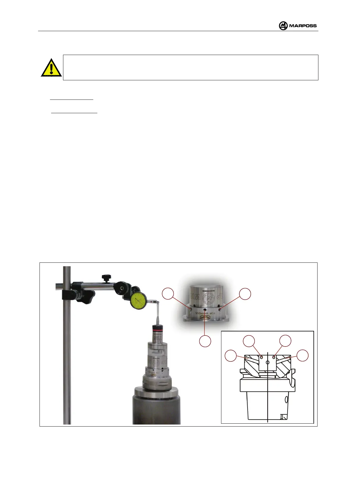
The fastening dowels are indicated by letter “A” in the Figure 4-13
. They are identified on the taper shank by
an engraving with a burin. These dowels are tilted to the X/Y plane.
The alignment dowels are indicated by letter “B” in the Figure 4-13. On the taper shank they can be
identified since they have no mark. These dowels are parallel to the X/Y plane.
For a correct fitting/alignment act as follows:
• Fit WRP45 transmitter into the taper shank making sure that there are no foreign bodies on the
pairing surfaces. Be careful while centering it. In this phase it will be already helpful for the operation.
•
Tighten the fastening dowels (A in the Figure 4-13) alternately until the plane of the WRP45
transmitter adheres to the taper shank plane. Let the WRP45 transmitter freedom of movement on
the X/Y plane to be able to align it. In this stage the torque wrench setting suggested is 8N/m; the
wrench tightens the spring.
•
System alignment. Use the alignment screws (B in Figure 4-13) to move the WRP4 - WRP45
transmitter on the X/Y plane in order to align the system within 10µm.
• Fastening to the taper shank. Now the WRP45 transmitter is aligned and it is necessary to fasten it to the
taper shank so that it does not lose alignment. Tighten the fastening screws (A in the Figure 4-13)
alternately until the WRP45 transmitter is locked. In this stage the torque wrench setting suggested is
2N/m. After tightening is completed it is advisable to check the alignment again.
•
At this point, proceed as follows:
o If the alignment is already satisfactory (10 µm) Tighten the fixing screws (B) in alternate
order. The recommended tightening torque during this phase is 2N/m. Once all the screws
have been tightened, it is best to re-check the alignment.
o If it is necessary to improve the alignment (e.g. 2.5 µm), adjust the screws (B) in order to
achieve the desired alignment, the carry out the final tightening phase (Figure 4-15 - Point 4).
Figure 4-13. Aligning and fitting the WRP45 transmitter on the taper shank.