WRS – Installation Manual
4.13 Description of the Receiver with Integrated Interface (WRI)
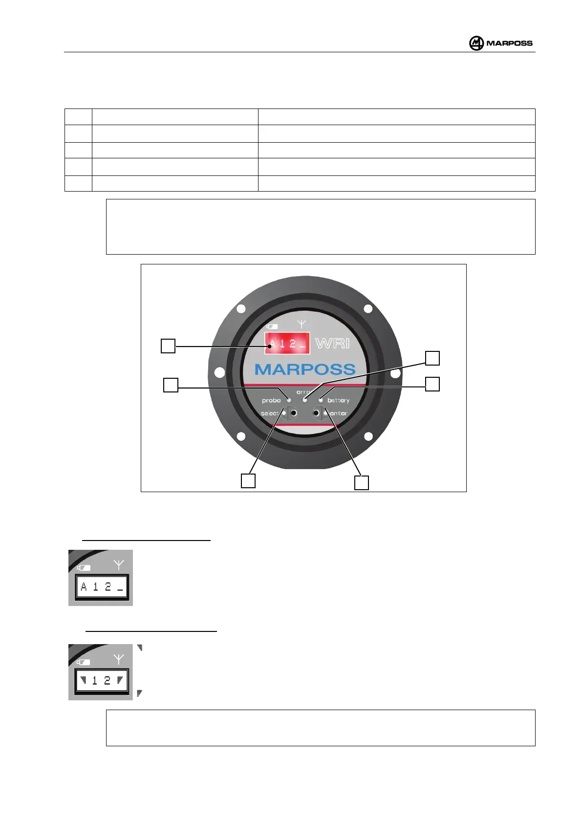
On the front of the receiver (Figure 4-53) there are:
A
Digital display 4 alphanumerical characters
B
Green LED “probe” PROBE1 and PROBE2 output statuses (see para. 4.12.6).
C
Red LED “error”
ERROR signal status (see para.4.12.8).
D
Yellow LED “battery”
WRP transmitter battery status (see para.4.12.7).
E/F
ENTER and SELECT optical keys Data display and programming
[
N.B.:
The "probe" LED flashes to indicate when the SELECT
function has been activated (optical
button F), whereas the “battery” LED indicates when the ENTER
function is activated (optical
button E). See par. 4.13.1
Figure 4-53. WRI receiver panel
With reference to Figure 4-53, there are reported the display screens available on display (A)
• Out of the measuring cycle:
A : Letter of the work sub-channel.
1 : Work channel (Tens).
2 : Work channel (Units).
_ : Bargraph of the noise Power on the channel.
• During the measuring cycle:
: Bargraph of the battery level.
1 : Work channel (Tens).
2 : Work channel (Units).
: Bargraph of the Power of the signal of the WRP - WRTS transmitter communication
with the WRI receiver.
Outside the measurement cycle it is possible to use the SELECT function to display the sub-
channel with the most recent battery level reading.