WRS – Installation Manual
The following table describes how to associate the transmitters with the corresponding START input:
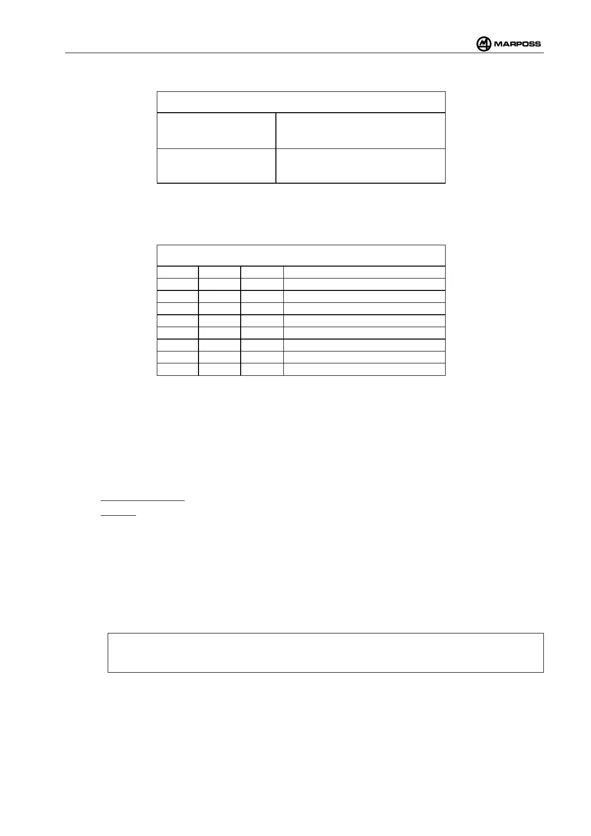
4-12. Associations between transmitters and START input
START1
SEL1 = 0 → PROBE A
SEL1 = 1 → PROBE C
START2
SEL1 = 0 → PROBE B
SEL1 = 1 → PROBE D
Table 4-13. Possible START and SEL1 signal combinations lists the correct combinations of the START1
and START2 signals and SEL1 input selection that are displayed by the WRI receiver if MS” (“Multiple Start”)
mode is enabled”:
Table 4-13. Possible START and SEL1 signal combinations
4.12.2 Staring the measurement cycle
4.12.2.1 Activating the transmitter
The transmitter is normally in the “out of cycle” condition, i.e. the radio connection is not active. In order to
perform a measurement cycle, it is necessary to activate communications by means of a radio signal.
The activation signal may be generated in two ways:
• Machine command. The transmitter is activated by a machine logic command (START input signal)
• Manual. The transmitter is activated via the ACT programming menu (see para. 4.15.5).
4.12.2.2 Activation time
The probe/receiver system is activated within a nominal interval that is less than the value set-up using
Speed Grade programming parameter:
• SPG = “0” activation delay < 2.1 s (low consumption)
• SPG = “1” activation delay < 1.1 s (typical consumption)
• SPG = “2” activation delay < 0.5 s (high consumption)
N.B.:
The fast activation option SPG = “2”
is indicated in the case of Heidenhain CNC and should only
be used when necessary due to the increased consumption levels (see para.4.2.6).
In the presence of noise or interference, the activation time may be longer (see para. 4.10.11 point 3).