WRS – Installation Manual
4.6 Aligning and installing the WRP60 transmitter on the taper shank
ATTENTION
The taper shanks used for the WRP60 transmitter are not compatible with the
transmitter.
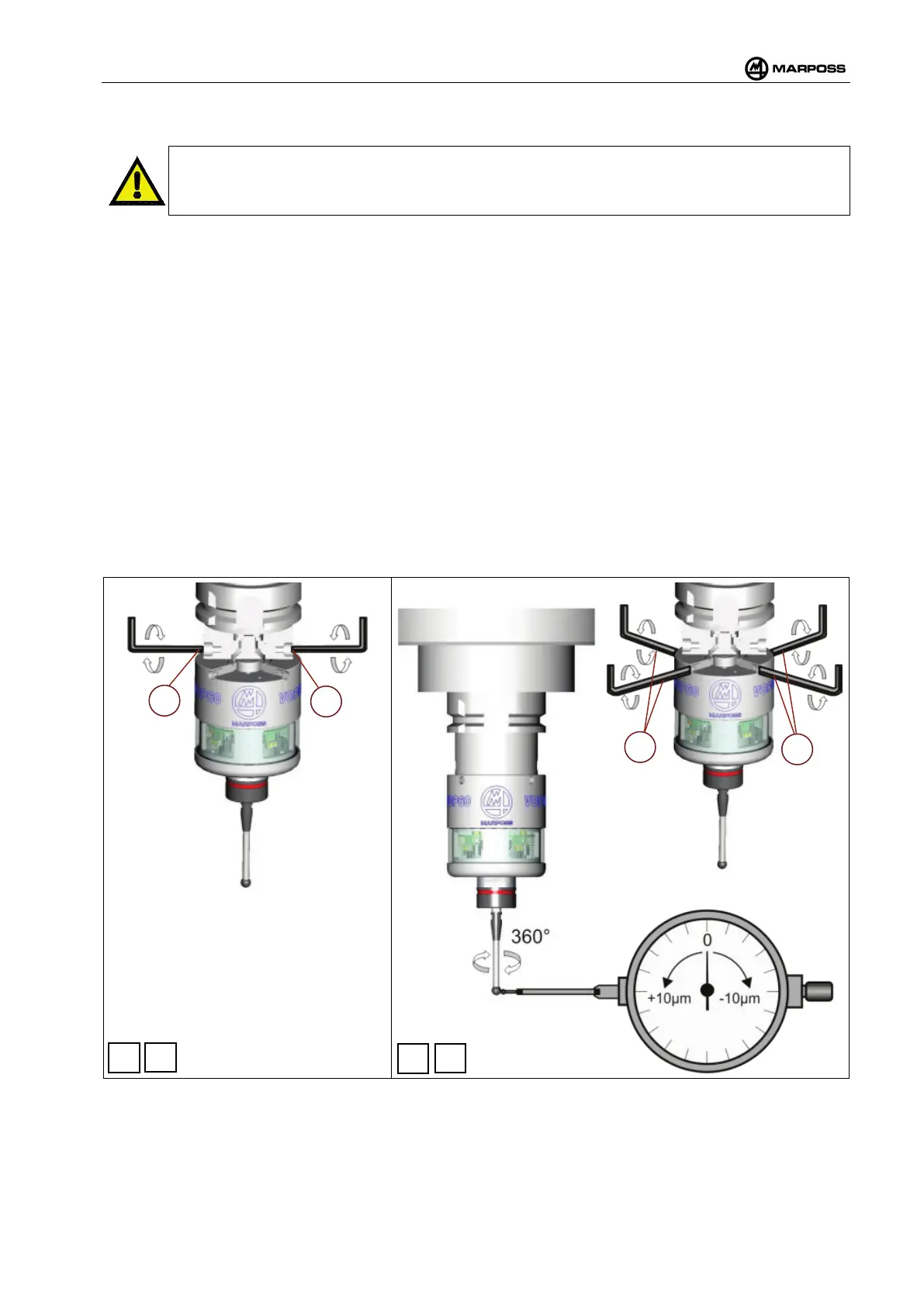
To align the WRP60 transmitter correctly on the taper shank, proceed as follows:
1. Insert the pin on the WRP60 into the cone and then tighten the 2 grub screws (A) (Figure 4-11 -
Point 1) until they make contact with the pin (suggested tightening torque: 1.5Nm), thus creating
friction against the pin, but without compressing it.
2. Using the alignment screws (B) move the WRP60 transmitter on the X/Y plane in order to align the
system to within in 10µm (Figure 4-15 – Point 2).
3. At this point the WRP60 transmitter is aligned and it must be secured to the taper shank so as not to
lose the alignment. Tighten the fixing screws (A) in alternate order until the WRP60 transmitter is
locked in position. The recommended tightening torque during this phase is 8N/m. Once all the
screws have been tightened, it is best to re-check the alignment (Figure 4-15 - Point 3).
4. At this point, proceed as follows:
o If the alignment is already satisfactory (10 µm) Tighten the fixing screws (B) in alternate
order. The recommended tightening torque during this phase is 2N/m. Once all the screws
have been tightened, it is best to re-check the alignment.
o If it is necessary to improve the alignment (e.g. 2.5 µm), adjust the screws (B) in order to
achieve the desired alignment, the carry out the final tightening phase (Figure 4-15 - Point
4).
Figure 4-15. Aligning and fitting the WRP60 transmitter on the taper shank.