WRS – Installation Manual
4.10.2 Installing the WRI receiver inside the machine
Whenever possible, position the WRI receiver inside the machine working area. Select the position so as to
guarantee a direct path between the WRI receiver and WRP transmitter, even while parts are being
machined. The area immediately surrounding the WRI receiver must also be kept free from all electrically
conductive objects. Ensure that the minimum distances defined by the following rules are respected (see
Figure 4-23):
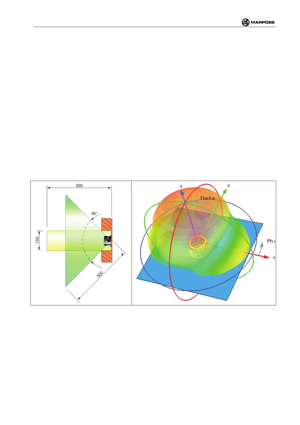
• An imaginary cone, having a hypotenuse equivalent to 500 mm, projected in front of the WRI
receiver must be kept free from all electrically conductive objects; the cone shall be defined by a
vertex positioned at the centre of the receiver contact plane and a minimum angle of aperture of 90°.
• An imaginary cylinder projected in front of the WRI receiver must be kept free from all electrically
conductive objects; the cylinder must be 150 mm in diameter and 500 mm long.
In order to ensure reliable communications, it is normally best to install the WRI receiver directly on the flat
surface of the machine metal structure. Figure 4-24 illustrates the regularity and uniformity of the radiation
diagram, note how the radiation is well distributed in all the possible directions in which the WRP transmitter
may be located. No electrically conductive objects or other materials are positioned in the vicinity, and the
surface located behind the WRI receiver acts as a reflector. The WRI body and window have been designed
for use in the most hostile working environments and conform to the IP68 protection rating, therefore no
additional protective measures are necessary; however, if the user wishes to introduce additional protection,
such a niche, it is very important to bear in mind the points mentioned above.
The dimensions indicated above represent the minimum requirements; the quality of
communications will be further improved if it is possible to increase the free space beyond these
limits.
Figure 4-23. Minimum dimensions of cone
and cylinder that must be kept free (in mm).
Figure 4-24.Radiation diagram for a WRI receiver mounted
on a flat metal panel.