WRS – Installation Manual
4.12 Description of input and output operating modes
4.12.1 Cycle start modes
The START signal may be configured according to the following operating modes.
1. Status mode
In this mode the START signal is interpreted on the basis of two logic levels:
• Logic low level: The voltage is not applied at the input
• Logic high level: The voltage applied at the input is correct.
The logic high level indicates the measurement cycle start request, whereas the low level indicates the
measurement cycle stop command (see Figure 4-42).
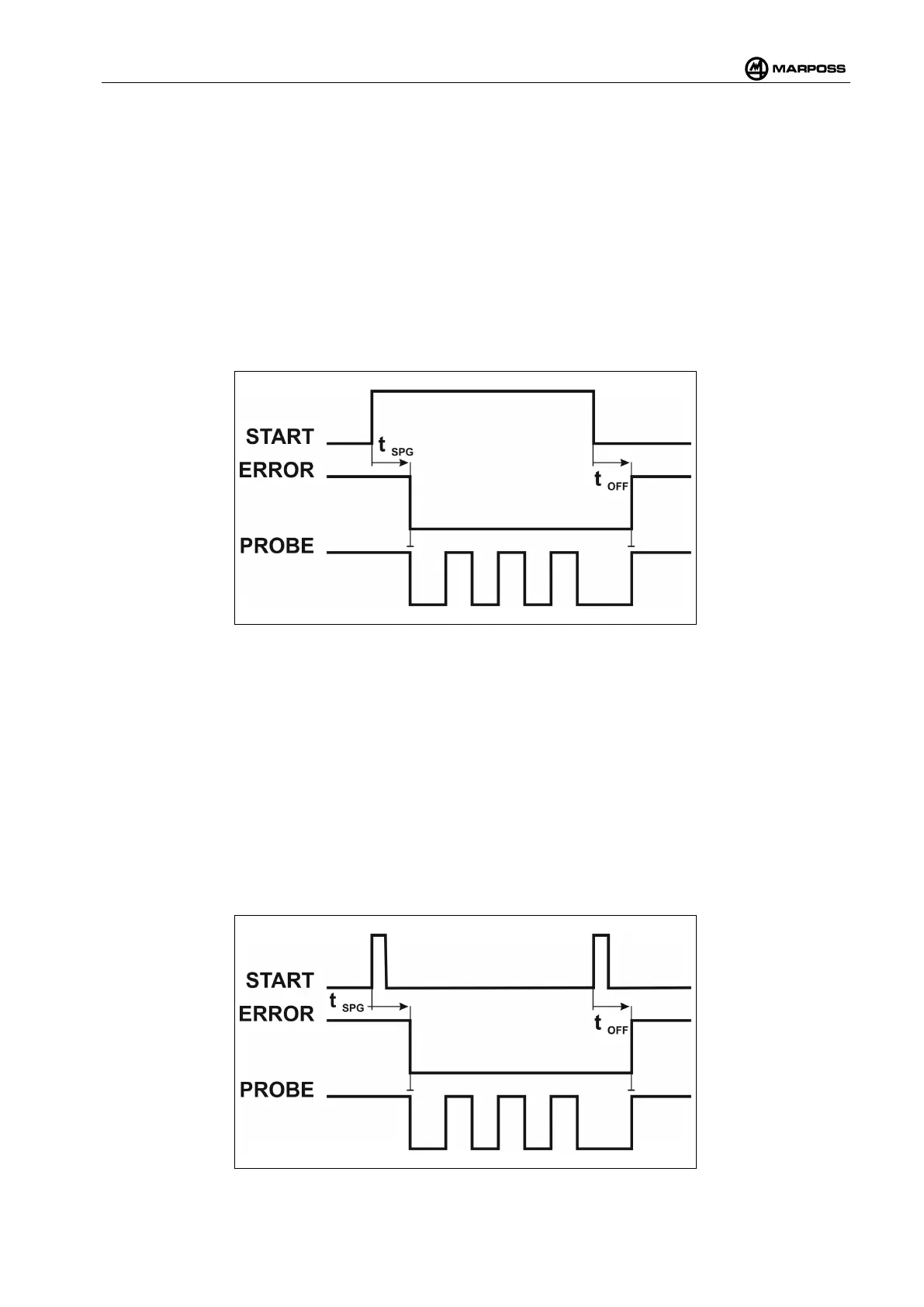
Figure 4-42. Example showing the cycle measurement with START in Status mode.
In Figure 4-42, when the START signal switches from the logic low to the logic high level, the WRP
transmitter is activated, after the activation delay (t
SPG
) defined in the Speed Grade (SPG) programming
parameters (see par. 4.15.4) has expired. In this example, after the probe has touched the part three times,
the cycle terminates, commutating the START signal to “logic low”. The connection is closed and the
ERROR and PROBE signals switch to the “out of cycle” state (i.e. the state they were in before the probe
was activated) after a delay (t
OFF
),
2. Pulse mode
In this mode, only the START signal leading edges are taken into account. When the system is not running,
a pulse is interpreted as a measurement cycle start request; whereas, when the system is running, it is
interpreted as a measurement cycle stop request. In other words, each pulse commutates the cycle state
(see Figure 4-43).
Figure 4-43. Example showing cycle measurement with START in pulse mode.