WRS – Installation Manual
4. INSTALLATION
4.1 WRP45 - Assembling the Transmitter
N.B.:
In most cases the transmitter is assembled when it is supplied, and it should not be disassembled
for any reason in order to avoid compromising the seal.
WARNING
In order to
ensure the correct tightening torque
between the parts, we recommend using two
wrenches (see Figure 4-1
tightening torque indicated in chart in.
Figure 4-1
. Example showing how to use
two assembly wrenches to tighten the parts.
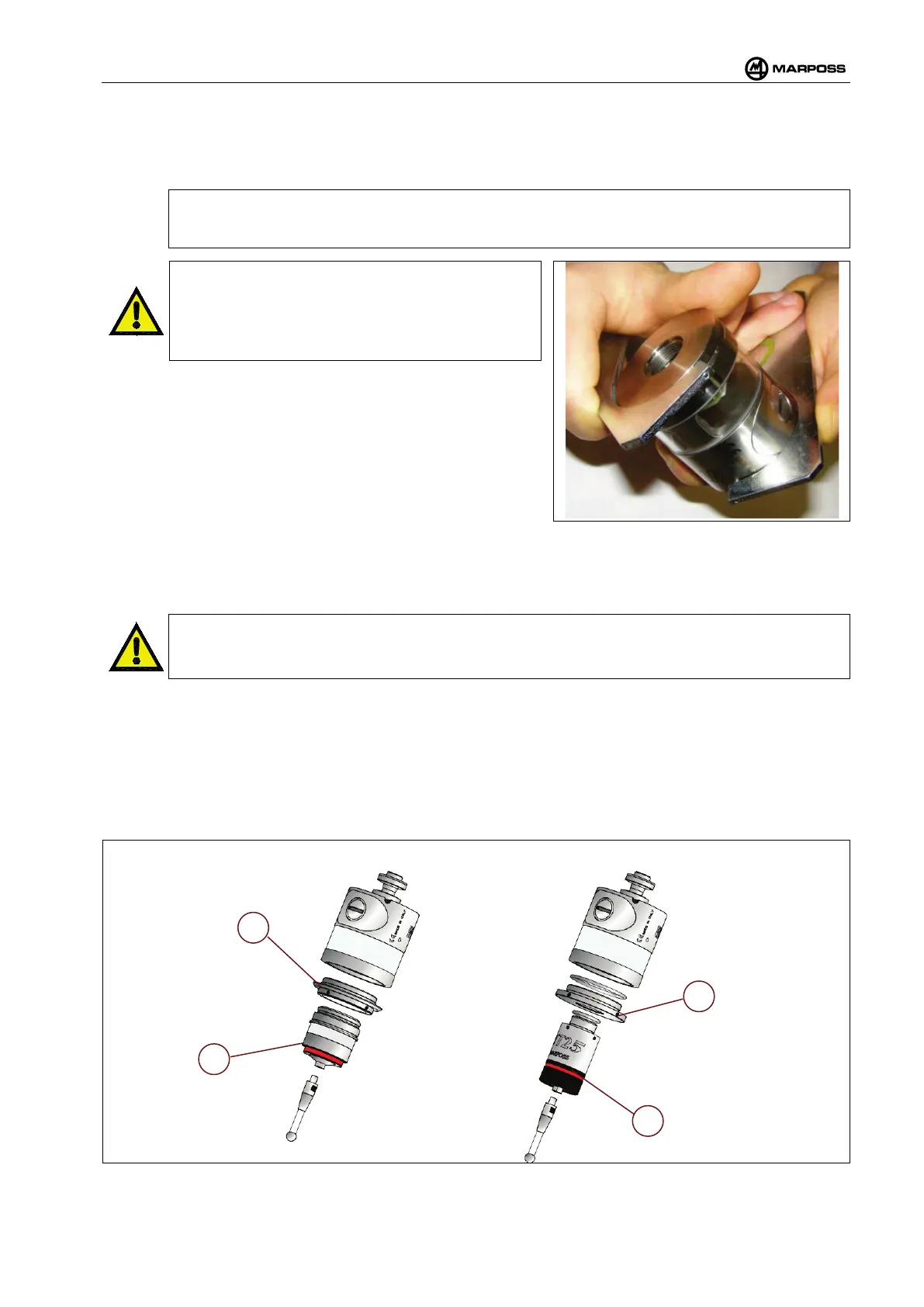
Fitting the probe – transmitter
Proceed as follows for fitting or removing the probe on/from the transmitter:
When fitting the probe, make sure that th
e seal rings are in very good conditions and correctly
positioned in their own seat.
TT30 probe
• Screw the flange (A2) to the transmitter with the wrench supplied with the equipment.
• Screw the probe (B2) to the flange using the wrench supplied.
TT25 - T25 - T25P probe
• Screw the flange (A1) to the transmitter with the wrench supplied
• Screw the probe (B1) to the flange using the wrench supplied.
After completing the operation, it is necessary to align the system (see section 4.3 on page 26).
FITTING THE TT30 PROBE FITTING THE T25 - TT25 - T25P PROBE
Figure 4-2. Fitting the probe – WRP45 transmitter.