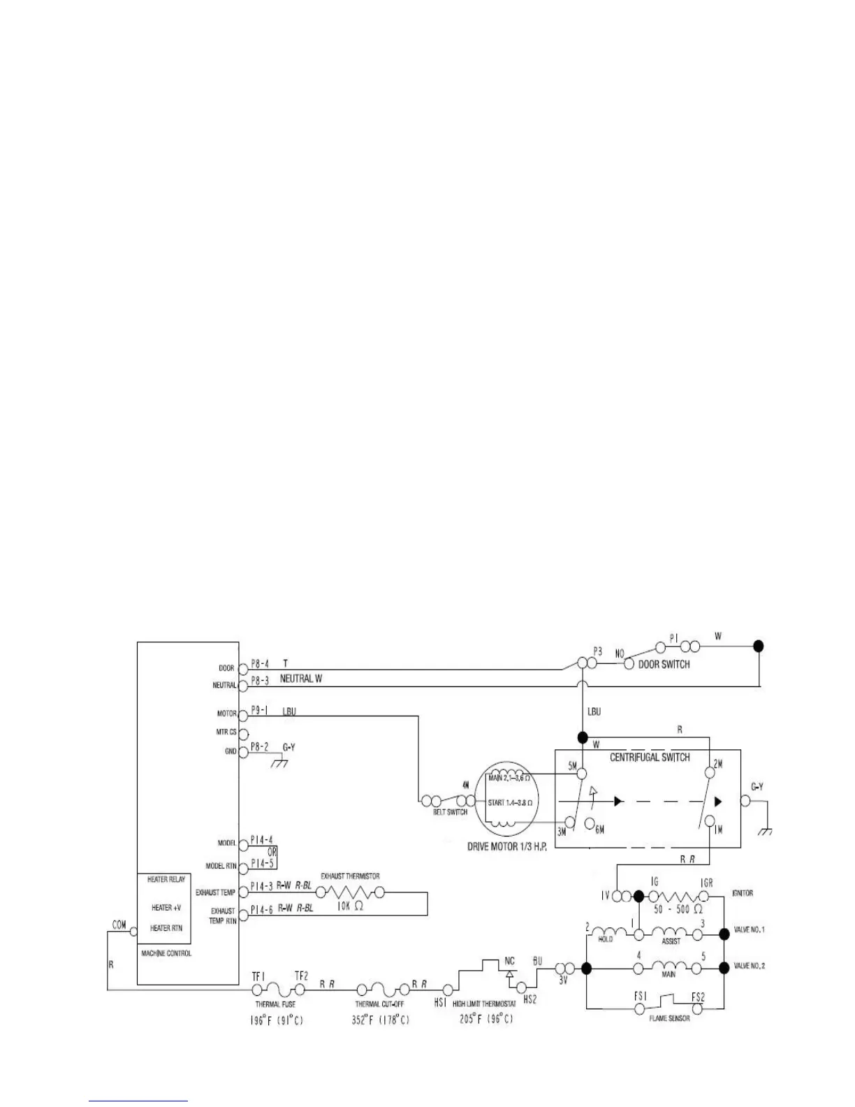
3-3
1. Thermal Fuse
2. Exhaust Thermistor
3. High temp cutout
4. High temp thermostat
5. Motor Switch 1M to 2M
6. Gas Valve Coils
Not so obvious is the door switch when open
will open the motor relay in the CCU and that
opens contacts 1 to 2 of the motor switch.
Using this same theory we can show that
if there is line voltage showing at the 2-pin
connector for the gas valve, then all of the
thermal components are closed and OK! We
would also know that the motor switch 1M
to 2M is closed as well, because one side of
the line voltage must pass through this motor
switch that is only closed when the motor is
running.
When WHITES AND COLORS is selected,
the high heat cycle is activated. The high temp
cycle uses the circuit that involves the 68.3°C
(155°F) setting for the exhaust thermistor.
After the cycle type is selected on all models,
the dryer motor circuit is energized. The motor
has power sent to both the Run and the Start
windings because the motor switch contacts
5 to 3 is closed. When the motor reaches run
speed the centrifugal switch snaps closed and
the motor switches change position. Motor
contact 5 continues to power the main motor
winding, but contact 3 becomes an open
circuit (innite Ω) to the start winding.
At the same time motor contact 1 closes to
2, which allows the completing of the heater
circuit. Now the blower, the drum, and the heat
are all working.
Notice the components in this gas heat circuit;
heat can be shut off by opening any of the in-
line components:




 To Next Page