125 of 271
Figure 3 - Screws On Back of Take-Up Lever Cam
6. Remove the screws mounting the z-shaft end plate to the take-up lever cam.
Figure 4 - Remove Hex Nut
7. Remove the M4 hex nut from the take-up lever cam and put it in the replacement cam.
8. Apply red loctite (MS 222) to the M4 screws and attach the z-shaft end plate to the take-up lever
cam. Make sure the M4 hex nut does not fall out of the recessed hexagonal hole in the take up
lever cam. Tighten the M4 screws to 10.5 in-lbs[1.2 Nm] of torque.
Figure 5 - Endplate w/Spring Pin Pressed in EndPlate- back view
9. Push the spring pin into the z-shaft end plate from the front until it is ush to the back of the end
plate (see gure 5).
•
Important: When inserting the spring pin, make sure the spring pin teeth are facing down.
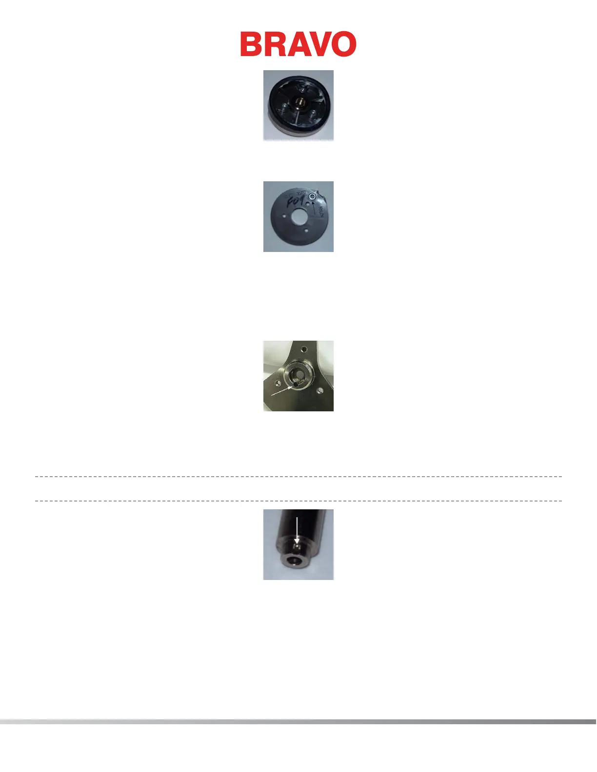
Figure 6 - Alignment Groove in Z-Shaft
10. Align the spring pin in the z shaft end plate with the groove of the upper z-shaft and press onto
the end of the shaft.
11. Push the spring pin back into the end plate if it slips out while pressing it onto the z-shaft.
12. Apply red loctite (MS 222) to the M5 screw and install it to the end of the upper z-shaft and tight-
en it to 66.5 in-lbs[7.5 Nm] of torque.

 Loading...