185 of 271
7. Pull the harness through the left to the back of the machine and remove the twist-lock cable tie
from the z-motor mounting bracket.
Figure 3 - Left Lower Arm Access Hole
8. Remove any twist-lock cable ties from the left LED cluster harness and pull it through the left wir-
ing access hole in the lower arm body to the Main PCB.
9. Remove the EMI Cover from the main control board.
Figure 4 - EMI Cover over Main Board
10. Remove the wire tie from the left and right LED cluster harnesses and disconnect the right LED
cluster harness from the Main PCB at connector location J9.
11. Connect the new LED cluster harness to the left LED cluster assembly and run it through the z-mo-
tor mounting bracket and use a twist-lock cable tie to tie it with the adjacent harnesses to the
z-motor mounting bracket (Figure 2).
12. Run the LED cluster harness following the adjacent harnesses down to and through the left lower
arm access hole (Figure 3).
13. Run the LED cluster harness through the left lower arm access hole to around the left inside pe-
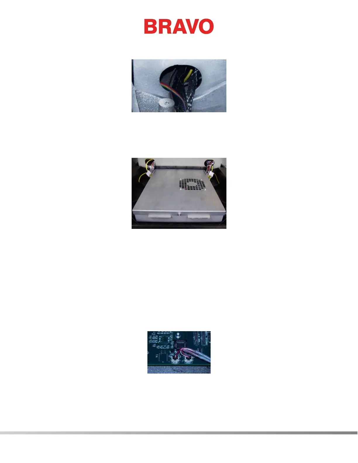
rimeter of the base and connect it to the Main PCB at connector location J9.
Figure 5 - LED Cluster Harnesses Connected at Main PCB
14. Place the LED cluster harnesses at the main PCB as shown in Figure 5 above.
15. Install the left upper arm front cover and tighten the screws to the torque specications.
16. Replace the EMI cover carefully.