189 of 271
8. Pull the harness to the back of the machine, remove any twist-lock cable ties that bundle it to
adjacent harnesses, all the way down to the right access hole to the Main PCB.
Figure 2 - EMI Cover over Main Board
9. Remove the EMI cover from the main control board.
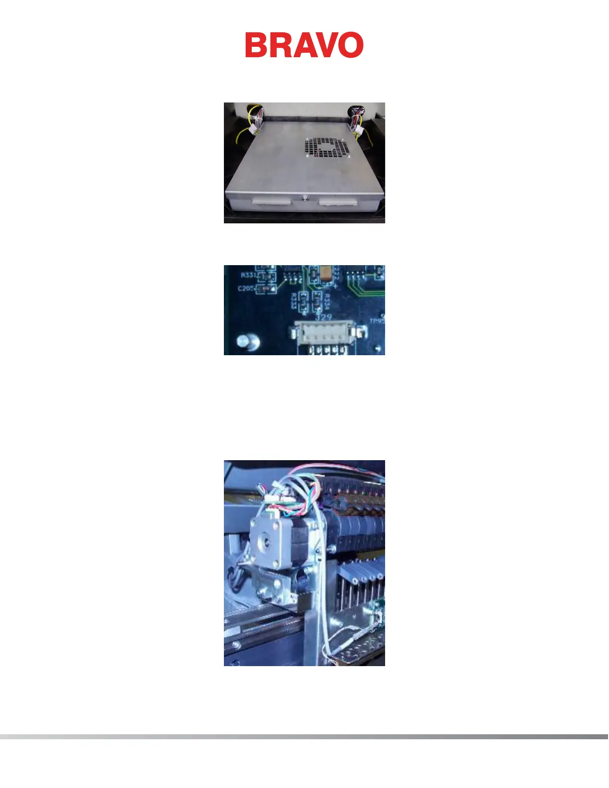
Figure 3 - Connection at Main PCB
10. Disconnect the thread break harness from the connector socket at location J29 on the Main
PCB and cut any remaining cable ties bundling the thread break harness to adjacent harnesses.
Remove the harness from the machine.
11. Connect the end of the thread break harness labeled “THREAD BREAK SENSOR PCB” to the con-
nector socket on the thread break sensor PCB.
Figure 4 - Routing of Harness to Top of Needlecase