130 of 271
Figure 2 - Z-Home PCB Mounting Bracket
•
NOTE: Make sure that the ag is centered front to rear between the sensors on the optical PCB.
Adjust PCB if required.
8. Tighten the screws to the torque specications and remove the xture.
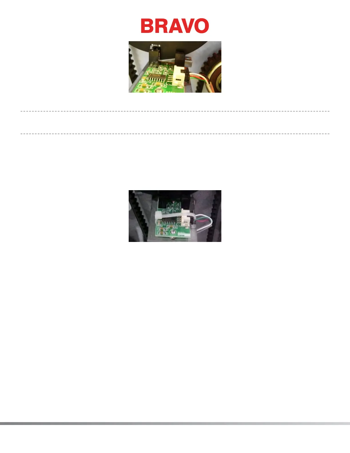
9. Connect the z-home harness lead into the PCB connector socket.
10. Use a small plastic cable tie and tie the connector snug by attaching the cable tie around the PCB
such that the cable tie holds the connector in place. Failure to do this might result in the connec-
tors coming loose which can create difculties in troubleshooting. See Figure 3.
Figure 2 - Cable Tie Around PCB
11. Reinstall the upper arm back cover and tighten the screws to the torque specications.
12. Reinstall the left and right arm covers and tighten the screws to the torque specications (use min-
imum torque required for clamping plastic materials).