79 of 271
Figure 3 - Y-Home Flag (Bottom View)
9. Loosen the screws mounting the Y-Home Flag to the bottom of the upper arm body on the left
side. The Y-home ag also serves as a wiring channel for the X/Y home harness (the rainbow col-
ored ribbon cable).
10. Move the Y-Home ag all the way to the front to a dead stop, then slowly move the y-home ag
towards the back just until the LED comes on and is brightly illuminated. Tighten the screws to the
Torque Specications as listed in that section.
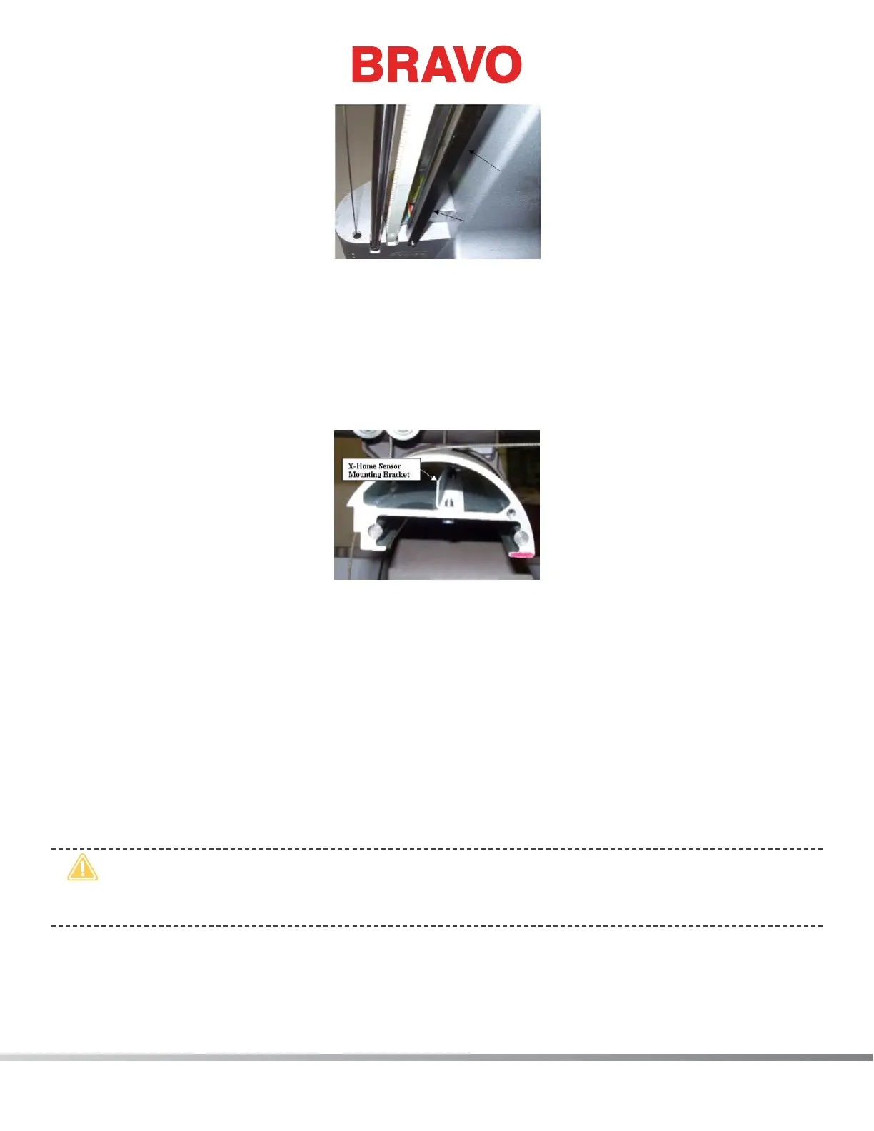
Figure 4 - X-Home Sensor Mounting Bracket
11. Loosen the two screws that mount the x-home sensor mounting bracket inside the x-beam. Move
the mounting bracket all the way to the left end of the beam and then push it back in to the right
just until the X-home LED comes on. Tighten the screws back to The torque specications.
12. Move the x-beam all the way to the back to a dead stop, observing the centering of the y-home
ag in between the sensors on the X/Y home PCB. Stop if the beam starts to hit one of the sen-
sors. If needed, loosen the screws on the Y-Home ag and center the ag between the optical
sensors. Move the x-beam all the way to the front to a dead stop and repeat the procedure at the
front. Move the beam back and forth a few times and make sure that the optical sensors on the
bottom of the X/Y home PCB do not hit the Y-home ag and the ag is approximately centered
on the ag.
•
CAUTION!! DO NOT release the E-Stop Button while the Y-Home Fixture is installed on the ma-
chine. Severe damage to the machine can occur if you release the E-Stop Button or attempt to
operate the machine with the xture in place.
13. Remove the X/Y-home xture rst and then release the emergency stop button by turning left or
right to release it.