Parameter Address
Default Min Max Unit Logic Diagram
[spacer]
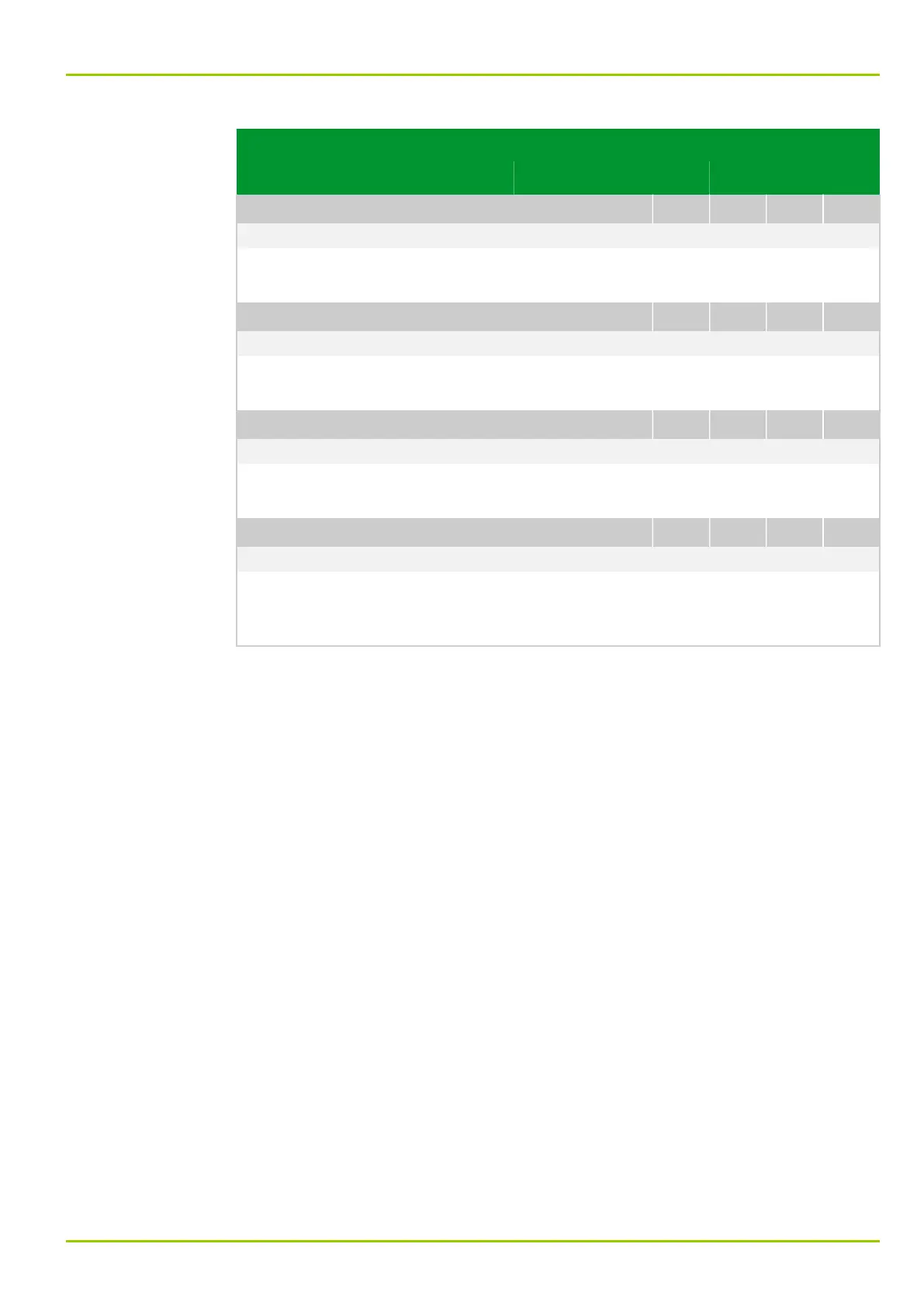
COMM2: Delta I
103 051
3.0 0.0 15.0 %Inom Fig. 3-14, (p. 3-19)
[spacer]
A measured current value is transmitted via the communication interface if it
differs by the set delta quantity from the last measured value transmitted.
[spacer]
COMM2: Delta f
103 052
2.0 0.0 2.0 %fnom Fig. 3-14, (p. 3-19)
[spacer]
The measured frequency value is transmitted via the communication interface if
it differs by the set delta quantity from the last measured value transmitted.
[spacer]
COMM2: Delta meas.v.ILS tel
103 150
3.0 0.0 15.0 Fig. 3-14, (p. 3-19)
[spacer]
The telegram is transmitted if a measured value differs by the set delta quantity
from the last measured value transmitted.
[spacer]
COMM2: Delta t
103 053
1 0 15 min Fig. 3-14, (p. 3-19)
[spacer]
All measured values are transmitted again via the communication interface after
this time period has elapsed – provided that transmission has not been triggered
by the other delta conditions.
7 Settings
P631
P631/EN M/R-11-C // P631-310-650 7-29