Parameter Address
Default Min Max Unit Logic Diagram
[spacer]
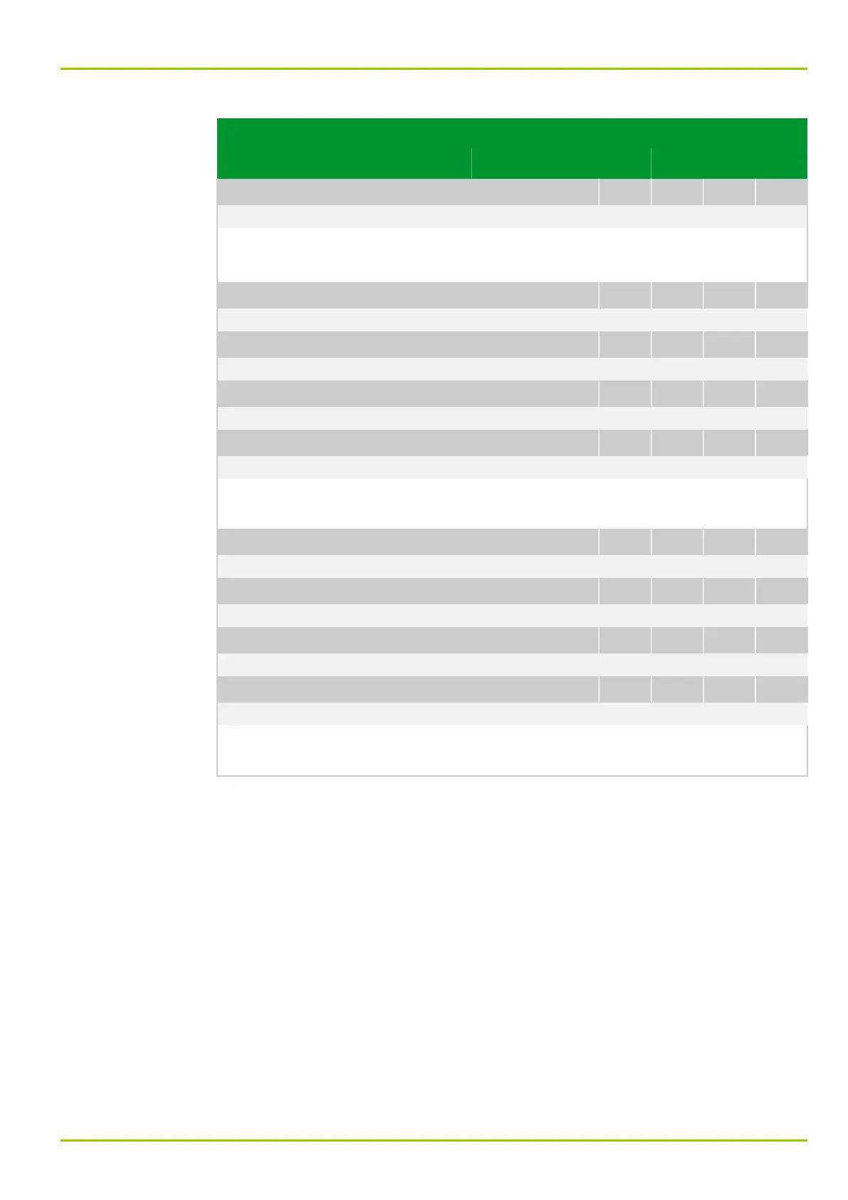
LOG_2: Time t2 output 4
050 015
0 0 60000 s
[spacer]
Settings for timer stage t2 for the respective outputs.
Note: This setting has no effect in the “minimum time” operating mode.
[spacer]
LOG_2: Sig.assig. outp. 1
064 000
061 000: MAIN: Without function
[spacer]
LOG_2: Sig.assig. outp. 2
064 002
061 000: MAIN: Without function
[spacer]
LOG_2: Sig.assig. outp. 3
064 004
061 000: MAIN: Without function
[spacer]
LOG_2: Sig.assig. outp. 4
064 006
061 000: MAIN: Without function
[spacer]
These settings assign the function of a binary input signal to the output of the
logic equation.
[spacer]
LOG_2: Sig.assig.outp. 1(t)
064 001
061 000: MAIN: Without function
[spacer]
LOG_2: Sig.assig.outp. 2(t)
064 003
061 000: MAIN: Without function
[spacer]
LOG_2: Sig.assig.outp. 3(t)
064 005
061 000: MAIN: Without function
[spacer]
LOG_2: Sig.assig.outp. 4(t)
064 007
061 000: MAIN: Without function
[spacer]
These settings assign the function of a binary input signal to the output of the
logic equation.
7 Settings
P631
P631/EN M/R-11-C // P631-310-650 7-103