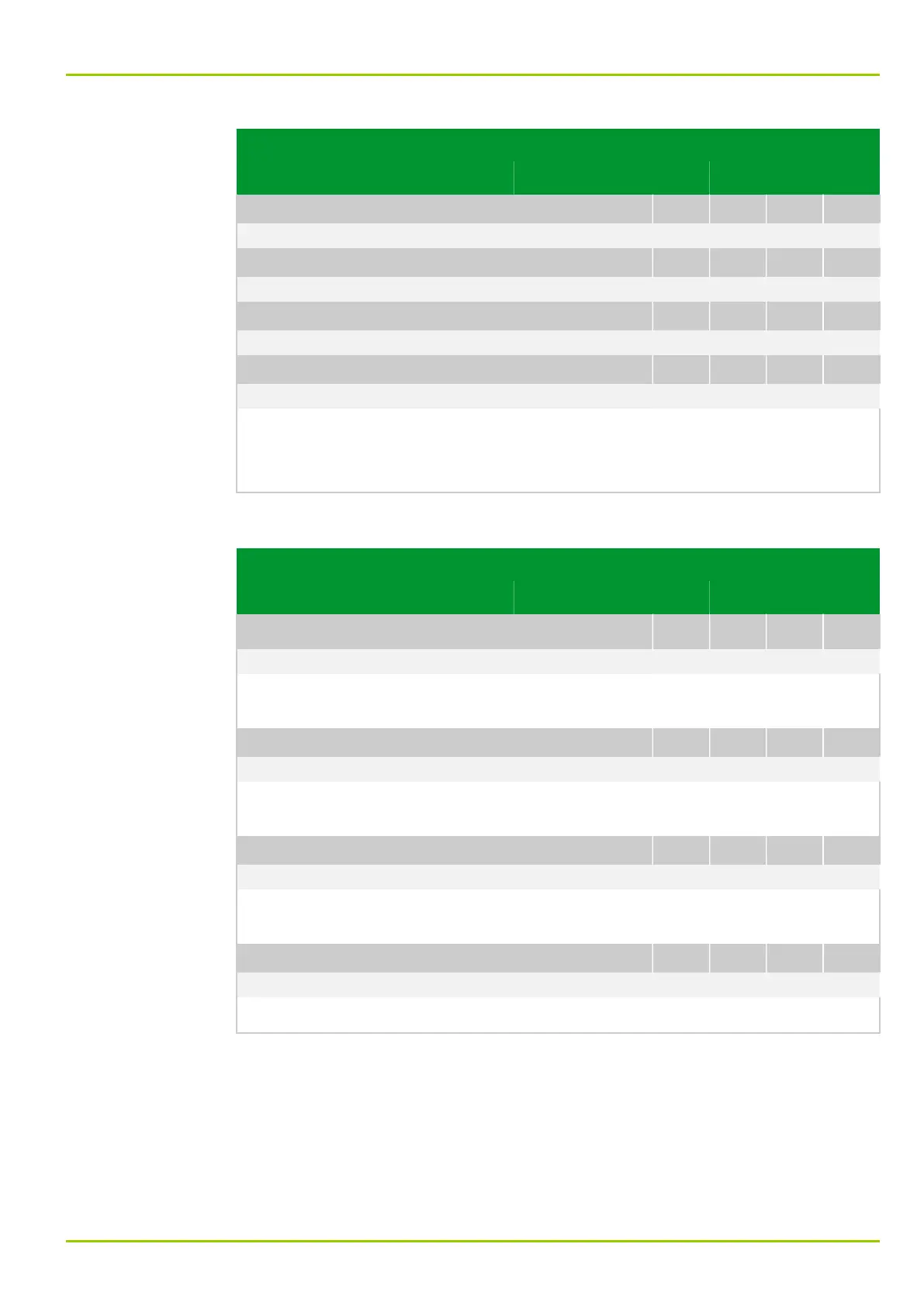
Parameter Address
Default Min Max Unit Logic Diagram
[spacer]
LED: State H20 green
085 166
0: Inactive
[spacer]
LED: State H21 green
085 169
0: Inactive
[spacer]
LED: State H22 green
085 172
0: Inactive
[spacer]
LED: State H23 green
085 176
0: Inactive
[spacer]
The state of the LED indicators is displayed as follows:
●
Inactive: The LED indicator is not energized.
●
Active: The LED indicator is energized.
8.1.1.3 Logic State Signals
Parameter Address
Default Min Max Unit Logic Diagram
Local control panel
LOC: Edit mode
080 111
0: No
[spacer]
Signal that the protection unit is in edit mode. As a standard this signal is linked
to LED: Fct.assig. H17 red.
[spacer]
LOC: Trig. menu jmp 1 EXT
030 230
0: No
[spacer]
Signal that menu jump list 1 is being triggered. (See the corresponding setting
at LOC: Fct. menu jmp list 1.)
[spacer]
LOC: Trig. menu jmp 2 EXT
030 231
0: No
[spacer]
Signal that menu jump list 2 is being triggered. (See the corresponding setting
at LOC: Fct. menu jmp list 2.)
[spacer]
LOC: Illumination on EXT
037 101
1: Yes
[spacer]
This signal shows that the backlighting for the front panel LCD is switched on.
8 Information and Control Functions
P631
P631/EN M/R-11-C // P631-310-650 8-25