Microtronix Access User Guide
11.2 WAN Interface – Synchronous Operation
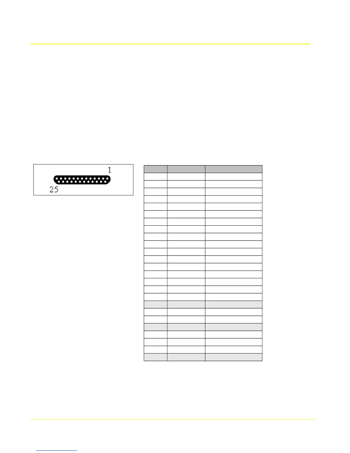
The WAN interface provides a choice of RS232 (V.24), RS530, RS530A, RS449, X.21, or V.35 signals
in a DB25F connector with standard RS530 DCE pin configuration.
When configured for synchronous or X.25 operation, the interface name is hdlc0 (WAN port 0), and
hdlc1 (WAN port 1) on the Access 4000 model.
In RS530, RS449, and X.21 modes, all signals are balanced and have 2 pins per function (A/B). In
RS232, only single ended signals are used with a common ground (SG), and the B pins are not used.
In V.35 mode, control signals are unbalanced, and data/clock signals are balanced. All balanced
signals (A and B) require twisted pair wires in the cable. Unbalanced signals (A only) do not.
The following table shows the RS530 pin configuration of the WAN port.
Note: Receive clock (RxC A/B) on pins 17/9 is bi-directional and depends on the clock configuration of
the port. Transmit clock (TxC A/B) is either output on pins 15/12 or input on pins 24/11 depending on
the clock configuration. Refer to the following sections for appropriate cabling for each clock
configuration.
92
Pin # Direction Signal Name
1
--- FG
2
input TxD A
3
output RxD A
4
input RTS A
5
output CTS A
6
output DSR A
7
--- SG
8
output DCD A
9
i/o RxC B
10
output DCD B
11
input (E)TxC B
12
output TxC B
13
output CTS B
14
input TxD B
15
output TxC A
16
output RxD B
17
i/o RxC A
18
19
input RTS B
20
input DTR A
21
22
output DSR B
23
input DTR B
24
input (E)TxC A
25