Microtronix Access User Guide
11.2.2.2 Tail Circuit Cables
If the port is configured to connect to another DCE using a tail circuit cable (Clock source =
TxFromRx), then a baud rate is chosen and the internal baud rate generator is used to source the
output RxC clock. Receive and transmit data use the ETxC (pin 24/11) to derive clocking.
Pin # Direction Signal Name
17 output RxC A
9 output RxC B
24 input TxC A
11 input TxC B
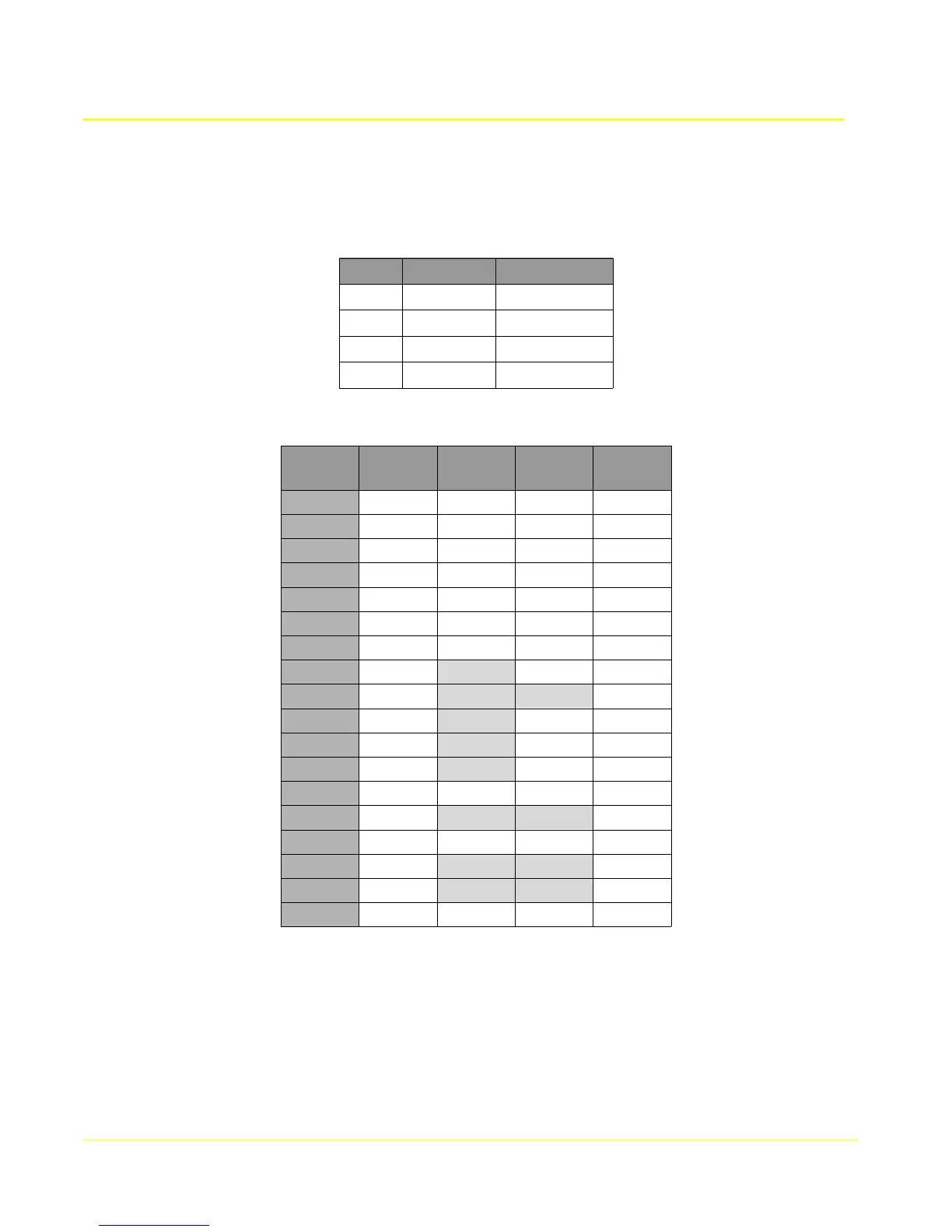
The following table shows the pin configurations and connector types for each supported interface type.
DB25M
RS530
DB25M
RS232
DB25M
V.35
M/34M
RS449
DB37M
1 1 1 A 1
2 3 3 R 6
3 2 2 P 4
4 8 8 F 13
6 20 20 H 12
7 7 7 B 19, 37
8 4 4 C 7
9 11 W 35
10 19 25
11 9 X 26
14 16 T 24
16 14 S 22
17 24 24 U 17
19 10 31
20 6 6 E 11
22 23 30
23 22 29
24 17 17 V 8
11.2.3 Split clock configuration
When the primary WAN port is configured for split clock (Clock source = TxInt), the clock pins are
configured as shown in the table below. The receive clock (pin 17/9) is generated internally, and the
transmit clock is derived from the external source on pin 24/11. Pins 15/12 are not used and should be
left disconnected. Since this is a custom configuration, the cable may be either straight through or
crossover, depending on the application.
97