Microtronix Access User Guide
11.2.2 Connecting to a DCE Device
Because the port is configured as a DCE, a crossover or tail circuit cable must be used to connect to
another DCE device (for example, a modem), so that the WAN port emulates a DTE.
11.2.2.1 Crossover Cables
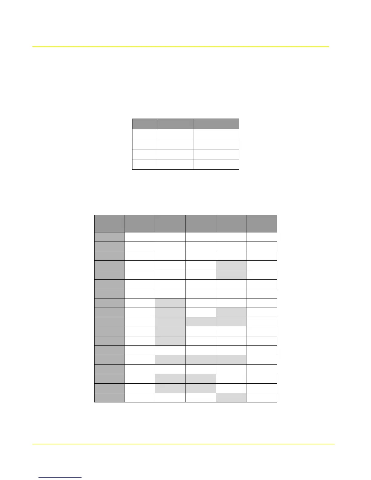
The port is configured (Clock source = External) to receive the clock signals from the DCE. The
receive clock is on pins 17/9, and transmit clock is on pins 24/11 (not the usual 15/12).
Pin # Direction Signal Name
17 input RxC A
9 input RxC B
24 input TxC A
11 input TxC B
Note: If the DCE uses the same source for generating the clock for both receive and transmit, then the
port can be configured for a single clock (Clock source = RxFromTx) on pins 17/9 and pins 24/11 may
be omitted.
The following table shows the pin configurations and connector types for each supported interface type.
The first column, DB25M, is the end of the cable that connects to the WAN port.
DB25M
RS530
DB25M
RS232
DB25M
V.35
M/34M
X.21
DB15M
RS449
DB37M
1 1 1 A 1 1
2 3 3 R 4 6
3 2 2 P 2 4
4 5 5 D 9
5 4 4 C 7
6,8 20 20 H 3 12
7 7 7 B 8 19,37
9 12 AA 13 23
11 9 X 26
13 19 25
14 16 T 11 24
16 14 S 9 22
17 15 15 Y 6 5
19 13 27
20 6,8 6,8 E,F 5 11,13
22,10 23 10 30
23 22,10 12 29,31
24 17 17 V 8
95