Microtronix Access User Guide
11.2.1 Connecting to a DTE Device
The primary WAN port is configured as a DCE, so can normally connect to a DTE device using a
straight through cable. The port is configured to provide DCE clock. The transmit clock (pins 15/12)
and the receive clock (pins 17/9) are sourced from a single baud rate generator, so the attached device
may use either signal as a single source for both receive and transmit clock.
If the port is configured to generate DCE clocks internally (Clock source = Internal), then a baud rate
is chosen and the internal baud rate generator is used to source the RxC and TxC clock signals. Pins
24/11 are not used and may be omitted from the cable.
If the port is configured to receive the clock from the DTE (Clock source = DTE), then the received
ETxC signal (pin 24/11) is used to generate the output DCE clock signals RxC and TxC.
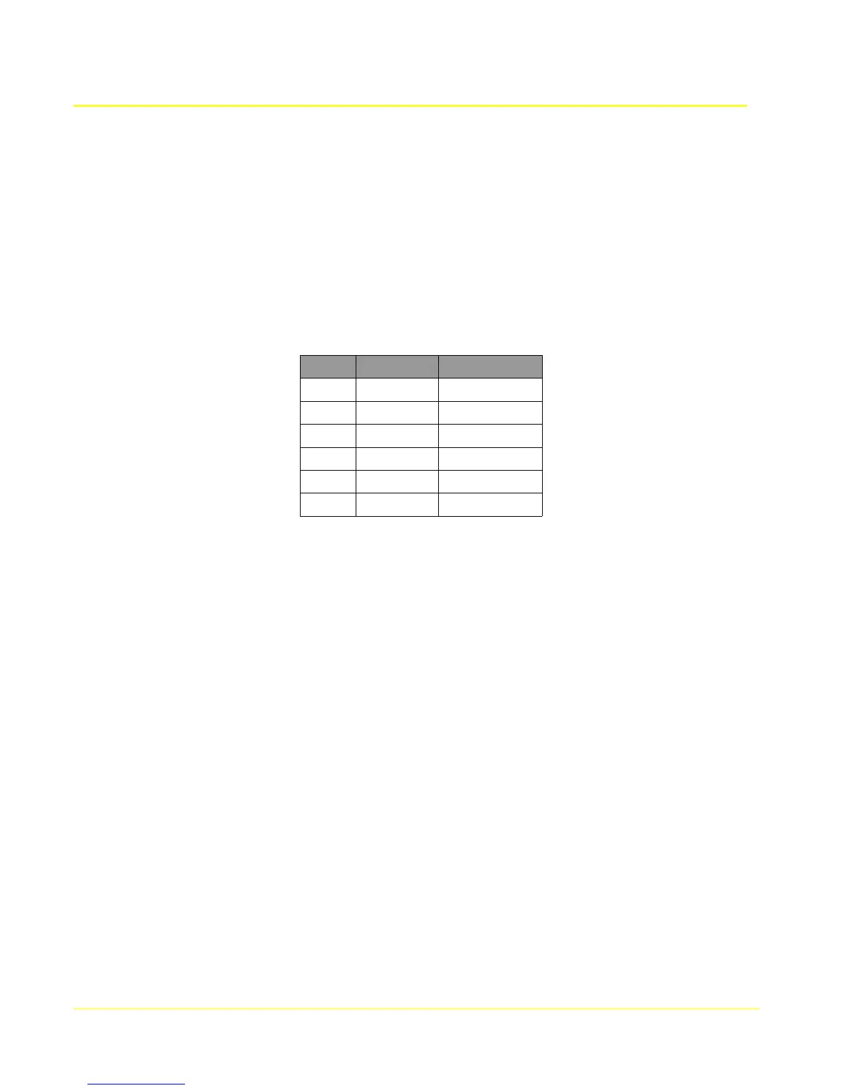
Pin # Direction Signal Name
17 output RxC A
9 output RxC B
15 output TxC A
12 output TxC B
24 input ETxC A
11 input ETxC B
93