PRELIMINARY
miniDSP Ltd, Hong Kong / www.minidsp.com / Features and specifications subject to change without prior notice 32
6.2 PREPARING FOR ACOUSTIC MEASUREMENT
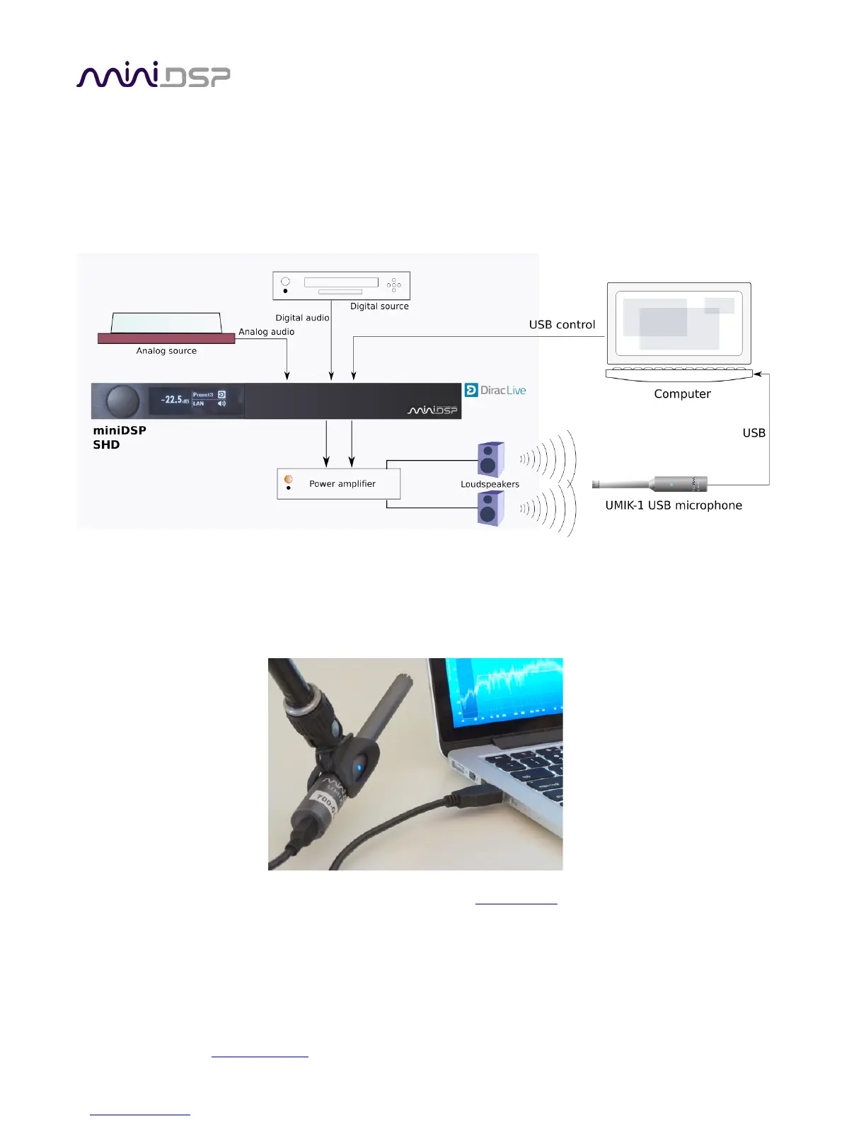
The figure below shows a typical connection diagram for performing acoustic measurement. No changes to
existing audio connections are needed. Simply:
1. Connect the supplied USB (type A to type B) cable from the processor to a USB port on the computer.
2. Connect the supplied USB (type A to mini type B) cable from the UMIK-1 to a USB port on the computer.
Place the UMIK-1 microphone into a microphone stand and position the computer and cabling so that there is
enough freedom of movement to move the microphone into the needed locations. A small tripod stand is
supplied with the UMIK-1, but a larger stand with boom arm can be used if desired. If necessary, a USB
extension (up to a total USB cable length of 5 meters) can be used. In larger spaces, an active USB repeater may
be needed.
Download the unique calibration file for your UMIK-1 from the UMIK-1 page by entering your microphone's
serial number. It is in the form xxx-yyyy and labelled on the microphone. Two calibrations files are provided, one
for when you point the microphone at or between the speakers, and a “90-degree” file for when pointing the
microphone at the ceiling. For stereo systems, we generally recommend pointing the microphone between the
two speakers.