PRELIMINARY
miniDSP Ltd, Hong Kong / www.minidsp.com / Features and specifications subject to change without prior notice 56
8.6 SAMPLE PLUGIN CONFIGURATIONS
This section provides a quick overview of a range of common configurations. For details on any of the processing
blocks mentioned, see Section 9.
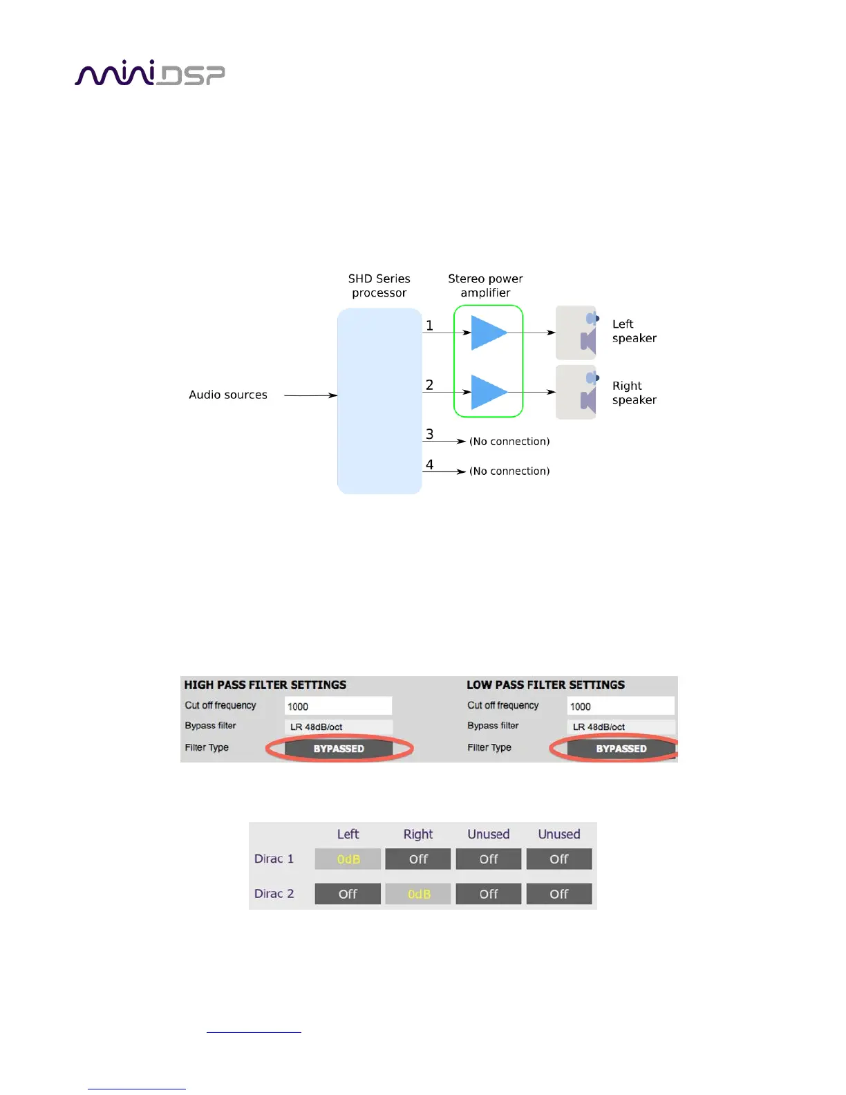
8.6.1 Stereo room correction
In a stereo room correction configuration, the plugin is set up to route the selected input through to output
channels 1 and 2. This diagram illustrates the connections:
Note: this is the default configuration of the SHD processor and is largely set up by a “Reset to Default”
operation.
On the Outputs tab:
• Rename the output channels (from left to right) to “Left”, “Right”, “Unused” and “Unused”.
• Mute channels 3 and 4 (labeled “Unused”).
• Check that the crossover filters of channels 1 and 2 (“Left” and “Right”) are bypassed:
On the Routing tab, set the matrix like this:
After you have set up the SHD plugin, save your configuration to a file. Then quit the SHD plugin, start DLCT and
run Dirac Live calibration as described in Sections 6 and 7.