Elevator Restriction Unit Installation and Configuration
Version 3.7 Telephone Access System Installation and Operation Manual 101 (119)
LT-969 Copyright January 2017
Relays 1 to 12. Screw terminal contacts for each relay.
6.6 Elevator Restriction Unit Configuration
The Elevator Restriction Unit ID is set using the eight position DIP Switch
labelled SW2 as shown in Figure 52.
The individual switches are numbered 1 to 8 from left to right, and are marked as
either ON or OFF. The first six switches (1, 2, 3, 4, 5 and 6) set the ID.
Note: Every Elevator Restriction Unit in a given TX3 System requires a
unique ID. Unit IDs must not be duplicated.
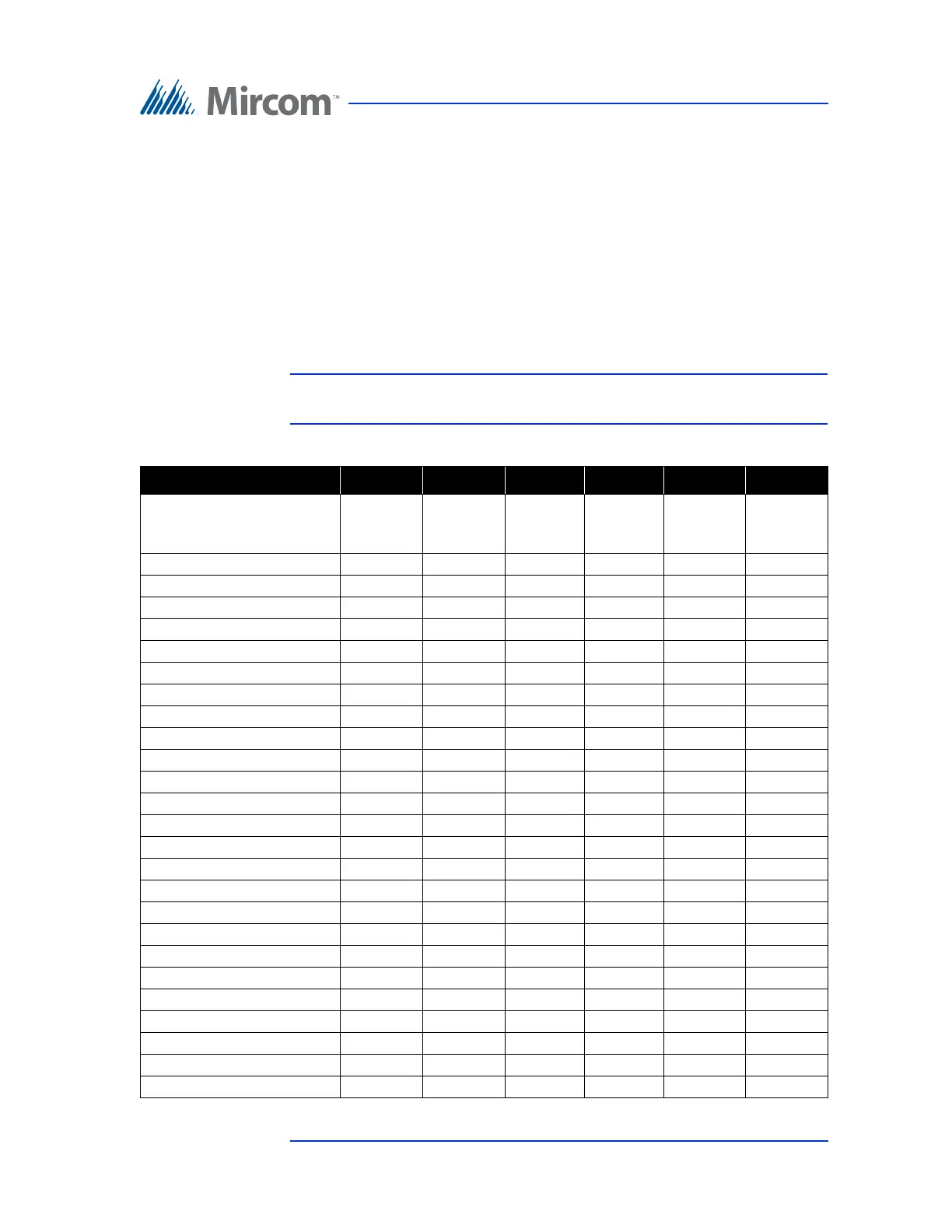
Table 7: Lobby Control Unit SW2 DIP Switch Settings
Lobby Control Unit ID # Switch 1 Switch 2 Switch 3 Switch 4 Switch 5 Switch 6
0 (not allowed as a Lobby
Control Unit ID 0 is used
for PC ID)
OFF OFF OFF OFF OFF OFF
1 ON OFF OFF OFF OFF OFF
2 OFF ON OFF OFF OFF OFF
3 ON ON OFF OFF OFF OFF
4 OFF OFF ON OFF OFF OFF
5 ON OFF ON OFF OFF OFF
6 OFF ON ON OFF OFF OFF
7ONONONOFFOFFOFF
8 OFF OFF OFF ON OFF OFF
9 ON OFF OFF ON OFF OFF
10 OFF ON OFF ON OFF OFF
11 ON ON OFF ON OFF OFF
12 OFF OFF ON ON OFF OFF
13 ON OFF ON ON OFF OFF
14 OFF ON ON ON OFF OFF
15 ON ON ON ON OFF OFF
16 OFF OFF OFF OFF ON OFF
17 ON OFF OFF OFF ON OFF
18 OFF ON OFF OFF ON OFF
19 ON ON OFF OFF ON OFF
20 OFF OFF ON OFF ON OFF
21 ON OFF ON OFF ON OFF
22 OFF ON ON OFF ON OFF
23 ON ON ON OFF ON OFF
24 OFF OFF OFF ON ON OFF
25 ON OFF OFF ON ON OFF