46 (119) Telephone Access System Installation and Operation Manual Version 3.7
LT-969 Copyright January 2017
TX3 System
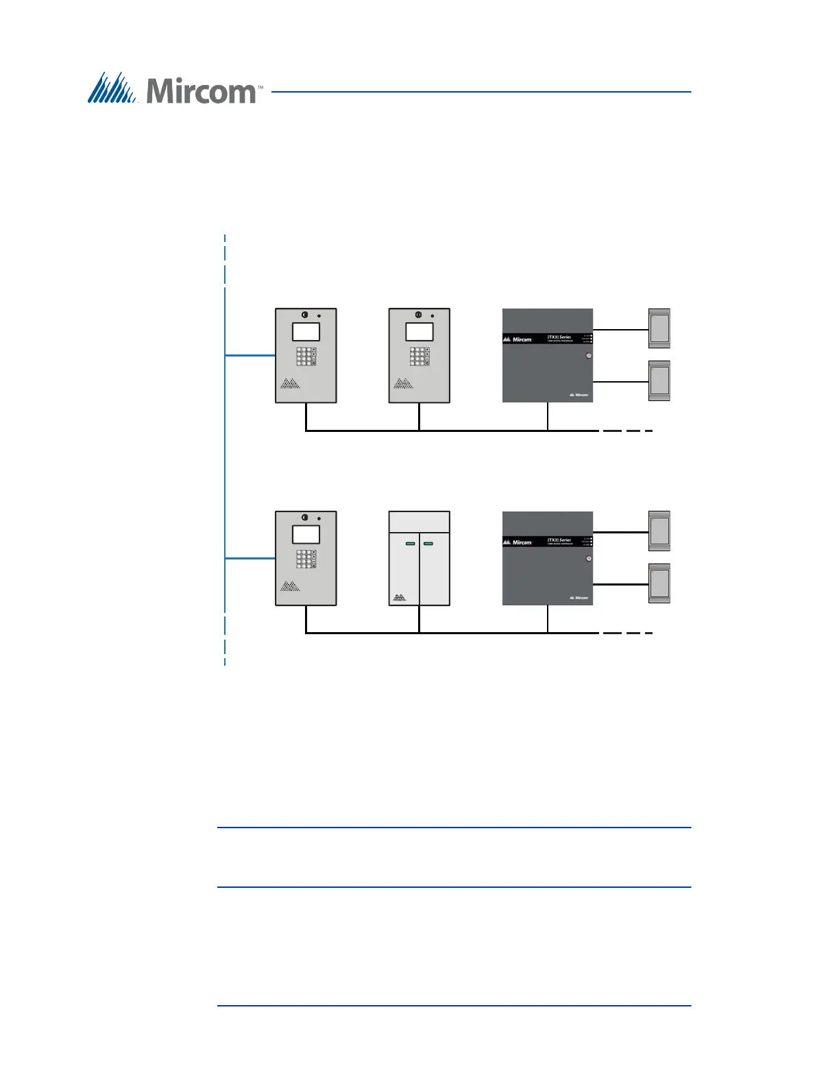
Figure 23 shows a configuration with TX3 devices connected on both an ethernet
TCP/IP network and on RS-485 subnetworks. Devices connected to a Master
Node’s RS-485 subnetwork are Slave Nodes to the Master Node. Each RS-485
subnetwork can have up to 63 devices connected to it; you can still have more
than 63 Master Nodes connected to the ethernet network.
Figure 23. Lobby control units using both ethernet and RS-485 networks
If you connect to the ethernet TCP/IP network with the TX3 Configurator, you
can configure any of the nodes in this configuration. If you connect directly to a
device using USB, a modem, or a COM port, you will only be able to configure
devices that are on the same RS-485 subnetwork as that device.
Note: There can only be one Master Node on an RS-485 subnetwork. That
is, you cannot connect one RS-485 subnetwork to another RS-485
subnetwork.
RS-485 Subnetwork
Lobby Control Unit
(Master Node)
Card Reader B
Card Reader A
Card Access Controller
(Slave Node)
Card Reader B
Card Reader A
Card Access Controller
(Slave Node)
RS-485 Subnetwork
Ethernet Network
2
ABC
3
DEF
1
5
JKL
6
MNO
4
GHI
8
TUV
9
WXYZ
7
PQRS
0
*
#
Lobby Control Unit
(Master Node)
2
ABC
3
DEF
1
5
JKL
6
MNO
4
GHI
8
TUV
9
WXYZ
7
PQRS
0
*
#
Lobby Control Unit
(Slave Node)
2
ABC
3
DEF
1
5
JKL
6
MNO
4
GHI
8
TUV
9
WXYZ
7
PQRS
0
*
#
Elevator Restriction Unit
(Slave Node)