54 (119) Telephone Access System Installation and Operation Manual Version 3.7
LT-969 Copyright January 2017
Lobby Control Unit Setup
4.2.5 Auxiliary Camera Supply
The camera supply connection is situated at the bottom right of the main
controller board and provides + 12 Vdc, 600 mA. The camera is controlled by one
of the general outputs. The camera’s positive terminal connects to the normally
open (NO) general output relay contact. The common (C) contact of the general
output relay connects to the + 12 Vdc supply terminal. The camera is typically
configured to operate when the main door is open.
4.2.6 LED/Lamp Supply
The LED/Lamp connection is situated at the bottom right of the main controller
board. This lamp is used with the paper directory models to illuminate the paper
directory.
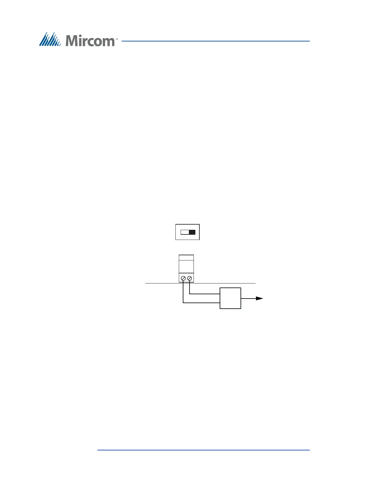
4.2.7 Power Supply
The power supply connection is situated at the bottom right of the main controller
board and receives 16 Vac, 40 VA. An external PS-4 or PS-4P plug-in
transformer connects to the power terminals. Refer to Figure 27 and Figure 30.
Figure 30. Power Supply
16 Vac IN
OFF ON
SW2
120 Vac
16 Vac
16 Vac transformer
(PS-4 or PS-4P)
ON/OFF Switch
Note: Use 18 AWG