TX3 System
Version 3.7 Telephone Access System Installation and Operation Manual 47 (119)
LT-969 Copyright January 2017
3.7 Lobby Control Unit Wiring
All units use the PS-4P transformer for the power supply. All wiring is a
maximum length of 1000 ft. The door strike power supply depends on the door
strike power requirements.
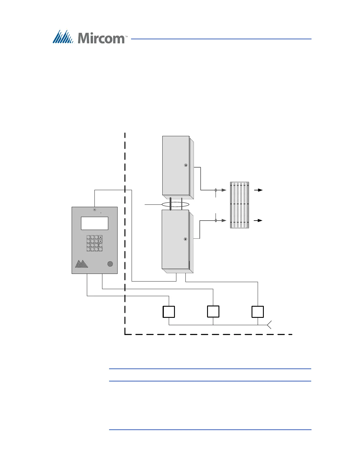
Figure 24 shows a typical wiring arrangement for the Lobby Control Unit.
Figure 24. Lobby Control Unit Wiring
Note: Install all transformers outside the Lobby Control Unit enclosure.
9106/
9406
Cables
2008/16
NSL Expander
Unit
1 2 3
4 5 6
7 8 9
* 0 # i
Resident’s
Telephone
Telephone
company
CA-71A
Or
RJ-71C
Blocks
Electrical room
Power
transformer
16VAC/40VA
PS-4 or PS-4P
Power
transformer
AC or DC Door
strike supply
T/R
T/R
120 VAC
60HZ
TX3-NSL-8M
NSL Control
Unit
Power
transformer
16VAC/40VA
PS-4 or PS-4P
T/R
Line1
Expansion
cables