NSL Relay Cabinet Installation and Wiring
Version 3.7 Telephone Access System Installation and Operation Manual 73 (119)
LT-969 Copyright January 2017
5.3 Wiring the TX3-NSL-8M Main Controller Board
The TX3-NSL-8M NSL Main Controller Board has both ribbon cable sockets
and screw terminals.
Attention: High voltages are present on this board during the ringing of suite
telephones.
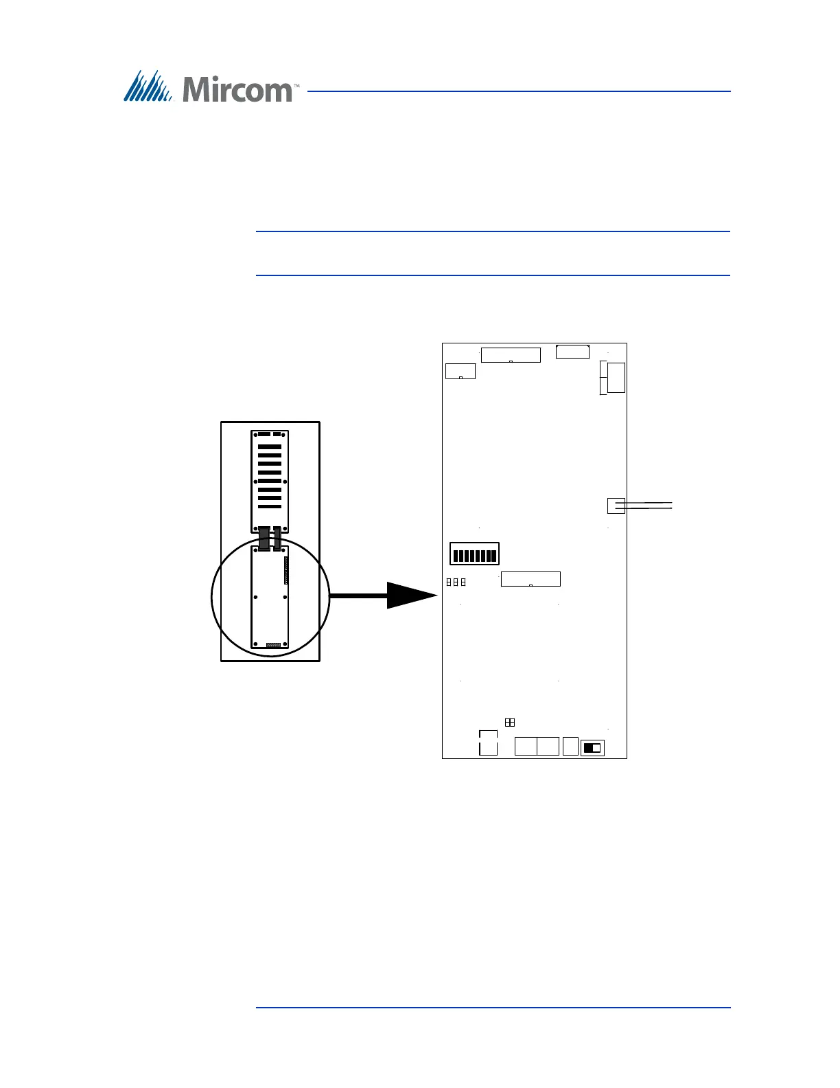
Figure 40 shows the general layout of the TX3-NSL-8M Main Controller board
components.
Figure 40. TX3-NSL-8M Main Controller Board
5.3.1 Connectors
USB. Computer connection for firmware download.
P3. Not used.
P4. Expansion to the NSL Controller back-plane.
SW1
ON OFF
1
8
SW2
USB
16V AC
IN
JW3
JW1 JW5
JW4 JW2
R
T
Telephone Line
from Lobby Panel
Main Controller
Board
R
T
R
T
Res.
Co.
P4
P5
P3
P6
TX3-NSL-8M Relay Control Unit
Expansion Connectors
TX3-NSL-8M Main Controller Board