Lobby Control Unit Setup
Version 3.7 Telephone Access System Installation and Operation Manual 53 (119)
LT-969 Copyright January 2017
Input 5. General Purpose. Input 5 is a general purpose input that, when
configured, activates a general purpose output to perform any required function.
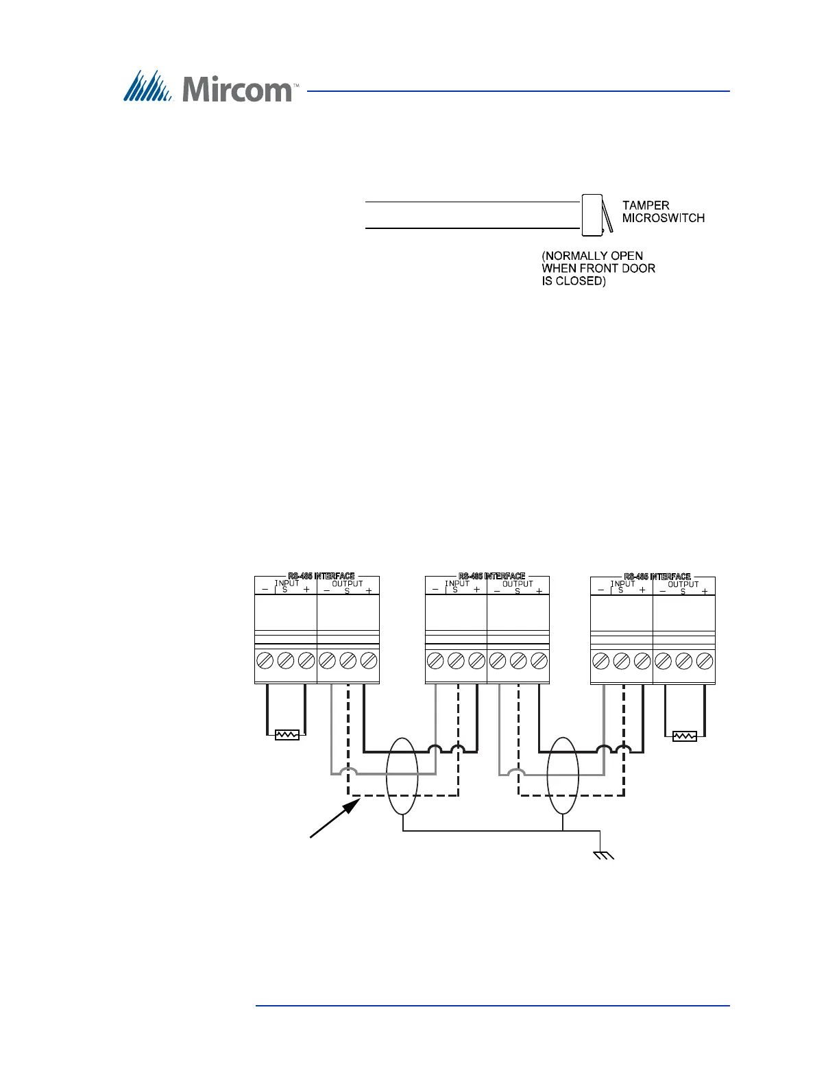
Figure 28. Tamper Switch
4.2.4 RS-485
22 AWG twisted pair, maximum length: 4000 ft (1219.2 m)
Mircom recommends shielded cable
An RS-485 terminal lets you easily connect multiple telephone, card access and
elevator restriction controllers across a network. The RS-485 connection is
situated at the bottom middle of the main controller board and consists of two
separate terminals, each for an input and output. See Figure 29.
Figure 29. RS-485 Connections
Connect to one of
the inputs on the
entrance panel
main board to
monitor the door
closure.
Panel 1
First panel on network
Panel 3
Last panel on networ
Panel 2
Optional common
reference connection
if available
Connect shield to chassis
ground on one panel only
120 Ω
120 Ω