40 (119) Telephone Access System Installation and Operation Manual Version 3.7
LT-969 Copyright January 2017
TX3 System
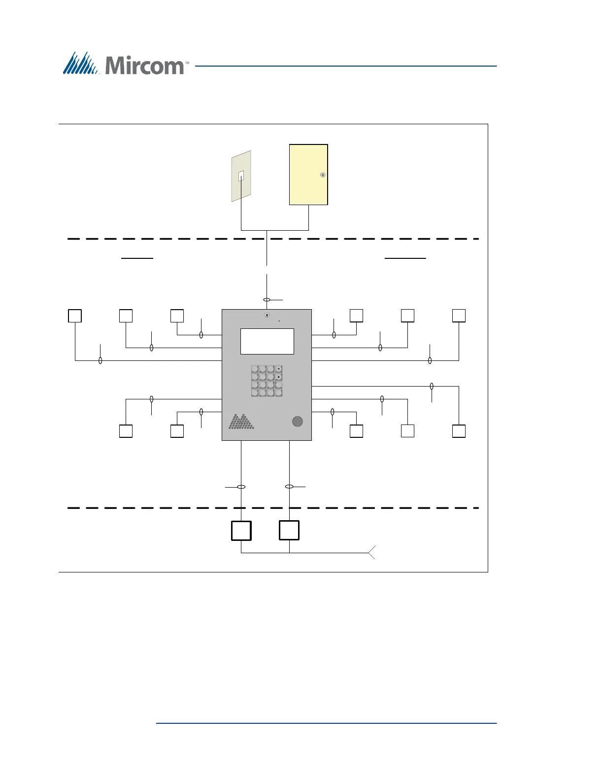
Figure 17 shows the various inputs to the panels.
Figure 17. Single Entrance System Wiring
3.3 Dual Lobby Control Units
Figure 18 shows a dual entry application for either an NSL type or ADC
connection type. The phone line from either the NSL control unit or an ADC
dedicated phone line is shared by both Lobby Control Units.
1 2 3
4 5 6
7 8 9
* 0 # i
Door
Strike AC
or DC
Aux Door
Form C relay
contact
General
purpose output
form C relay
contacts 1
General
purpose output
form C relay
contacts 2
1 pair
18 AWG
1 pair
18 AWG
3 wires
22 AWG
3 wires
22 AWG
1 pair
18 AWG
12 VDC/0.5A
Aux power
LED lamp
Supply (only
for paper
directory)
1 pair
18 AWG
Postal
Lock
Main Door
Sense
Fire panel
over-ride
1 pair
22 AWG
1 pair
22 AWG
1 pair
22 AWG
General
purpose
input 1
General
purpose
input 2
1 pair
22 AWG
1 pair
22 AWG
INPUTS OUTPUTS
Lobby
Control Unit
Electrical room
120 VAC
60HZ
Power
transformer
16VAC/40VA
PS-4 or PS-4P
NSL
Control
Unit
OR
Telephone outlet
Central office line
T/R
T/R
Power
transformer
AC or DC Door
strike supply
Line1
1 pair
Telephone
wire
Electrical room
18 AWG
18 AWG