60 (119) Telephone Access System Installation and Operation Manual Version 3.7
LT-969 Copyright January 2017
Lobby Control Unit Setup
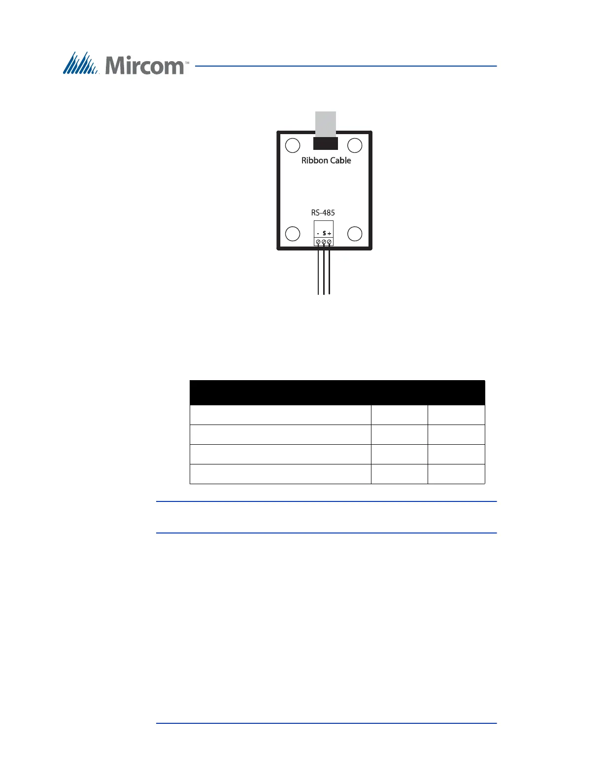
The module has an RS-485 connector as shown in Figure 35.
Figure 35. RS-485 Add-on Module
For a description on how to install the RS-485 Add-on Module see the USB to
RS-485 Adapter Installation Instructions LT-6027.
Note: For the main application of the RS-485 Add-on Module, JW1 and
JW2 should both be shorted.
4.7 Guard Phone Module
The TX3-GPM Guard Phone Module mounts above the TX3 Lobby Control Unit
main board on the top left hand side. See Figure 25.
The module has two connectors, an RJ-11 connector and a ribbon cable as shown
in Figure 36.
Table 1: RS-485 Add-on Jumper Settings
Mode JW1 JW2
No termination Open Open
AC termination 120R + 1nF Short Open
No termination Open Short
DC termination 120R (Factory Default) Short Short