Lobby Control Unit Setup
Version 3.7 Telephone Access System Installation and Operation Manual 51 (119)
LT-969 Copyright January 2017
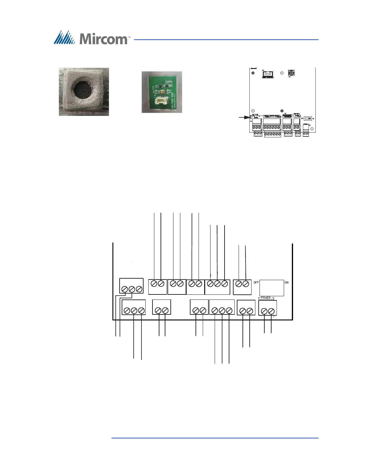
• If the panel has the MC-012 microphone, open JW11.
Figure 26 Microphones and JW11
4.2 Controller Board Connectors - Bottom
Figure 27 shows the connectors at the bottom of the controller board.
Figure 27. Controller Board Connectors - Bottom
MC-012 microphone
JW11 off or open
MC-009 microphone
JW11 on or closed
LED/LAMP
Supply
Speaker
Connection
Input 1
Input 2 Input 3 Input 4
Input 5
Camera Supply
Power Supply for TX3
(use 18 AWG)
RS-485 OUT
- +
- +
- s +
RS-485 IN
- s +
- +
- +
+--++-
+-
+-
Microphone
Connection
 Loading...


