58 (119) Telephone Access System Installation and Operation Manual Version 3.7
LT-969 Copyright January 2017
Lobby Control Unit Setup
• call is finished
• call is connected
• access is granted
• access is denied
• system is normal
4.4 Modem Module
Note: The Modem Module is designed to work only with POTS (plain old
telephone system) lines.
Attention: If you use the Modem Module to connect to and configure a Touch
Screen, then you cannot configure the Touch Screen locally.
The Modem Module is located above the TX3 Lobby Control Unit controller
board on the bottom left hand side. See Figure 25.
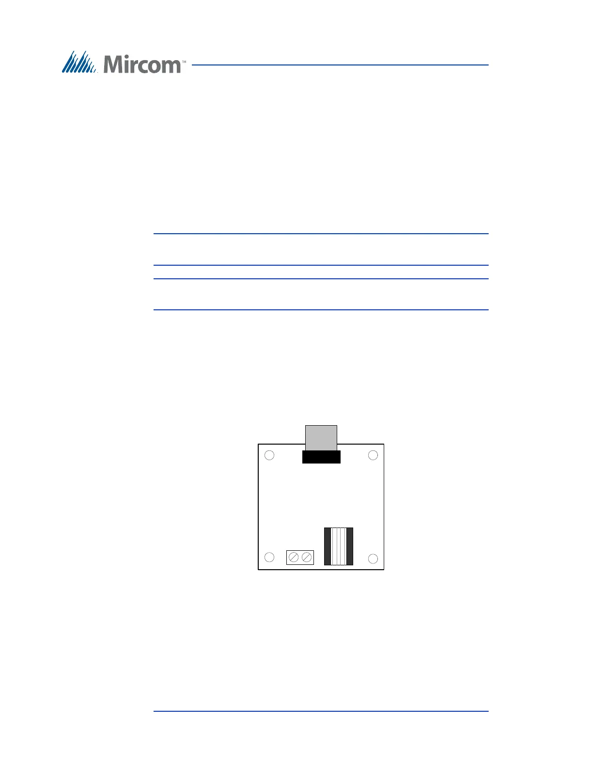
The module has two telephone connectors; an RJ-11 connector and a terminal
block as shown in Figure 33. The terminal block T/R line is polarity insensitive
and can be reversed.
The ribbon cable connects to the P4 connector on the controller board.
Figure 33. Modem Module Telephone Connectors
For a description on how to install the modem board see the Modem Manual
Installation Instructions LT-971.
MODEM MODULE
Tip Ring
RJ-11
connector