78 (119) Telephone Access System Installation and Operation Manual Version 3.7
LT-969 Copyright January 2017
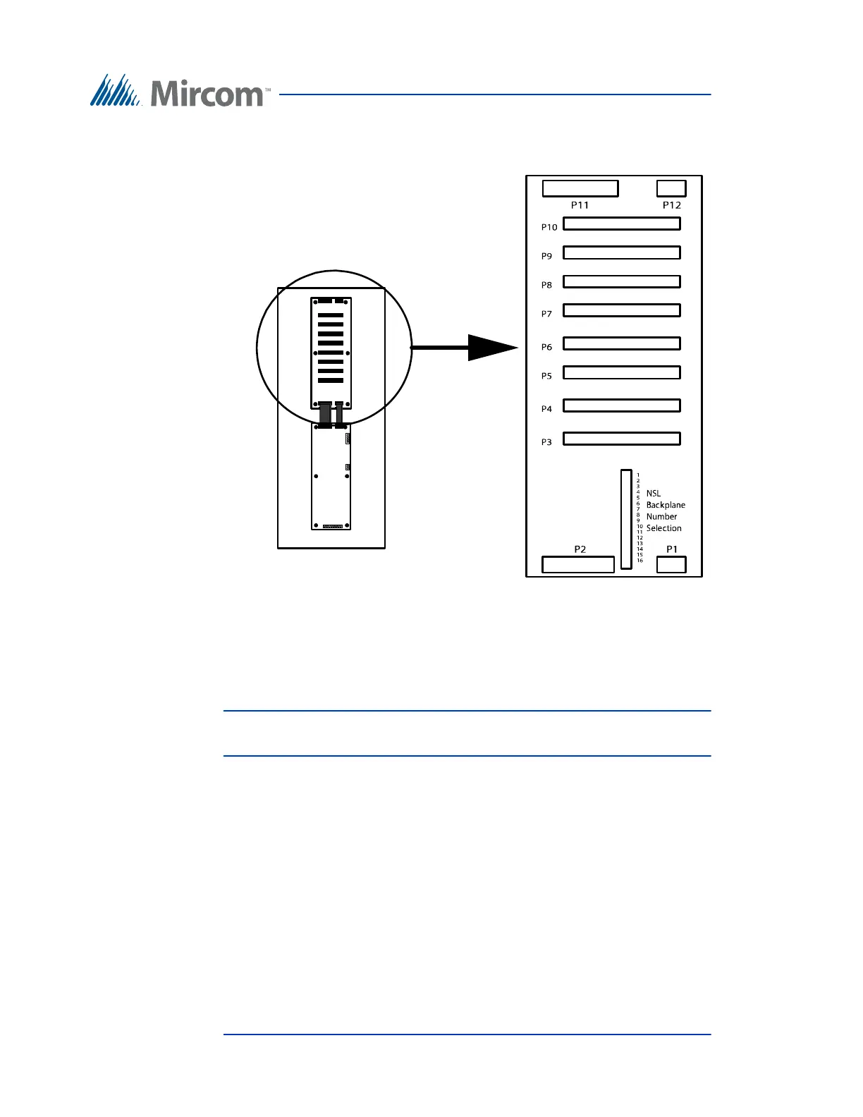
NSL Relay Cabinet Installation and Wiring
NSL Backplane Number Selector. (located between P1 and P2).
Figure 43. NSL Backplane
Attention: High voltages are present on this board during the ringing of suite
telephones.
5.3.9 Using NSL with Phone Lines that Provide DSL Service
If the building's telephone lines provide both DSL (digital subscriber line) and
POT (plain old telephone) services then the ADSL-100 filter module is required
to filter data signals. This filter module is installed between P4 on the NSL
Controller board and P1 on the first Back Plane board that connects to it. Refer to
the figure below for details on connecting the ADSL-100 module.
2016 NSL Unit Relay Backplane Boards
TX3-NSL-8M Relay Control Unit