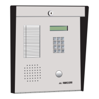
TX3 System
Version 3.7 Telephone Access System Installation and Operation Manual 37 (119)
LT-969 Copyright January 2017
3.1 TX3 System
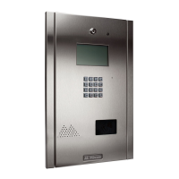
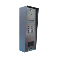
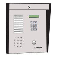
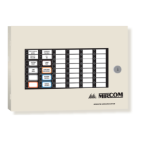
The TX3 Lobby Control Unit may be networked with a combination of Elevator
Restriction Units and Card Access Units through a peer-to-peer RS-485
connection.
The TX3 system is capable of providing ADC or NSL telephone access from a
single panel or from a networked system.
The No Subscriber Line (NSL) controller does not require an outside telephone
service and calls residents directly using the existing building’s resident
telephone lines. The NSL system uses the TX3-NSL-8M NSL units and TX3-
8EC/16 NSL expanders situated in the electrical/telephone rooms.
The Auto Dialer Controller (ADC) uses the existing outside telephone lines to
call residents.
Each outside telephone line requires a separate line to the entry control panel.
The following figures depict various TX3 network scenarios.
Note: Install all transformers outside the Lobby Control Unit enclosure.
All wiring is a maximum length of 1000 ft. The RS-485 wiring maximum length
is 4000 ft.
All units use the PS-4P transformer for the power supply. The door strike power
supply depends on the door strike power requirements.
 Loading...


