Lobby Control Unit Setup
Version 3.7 Telephone Access System Installation and Operation Manual 55 (119)
LT-969 Copyright January 2017
4.3 Controller Board Connectors - Top
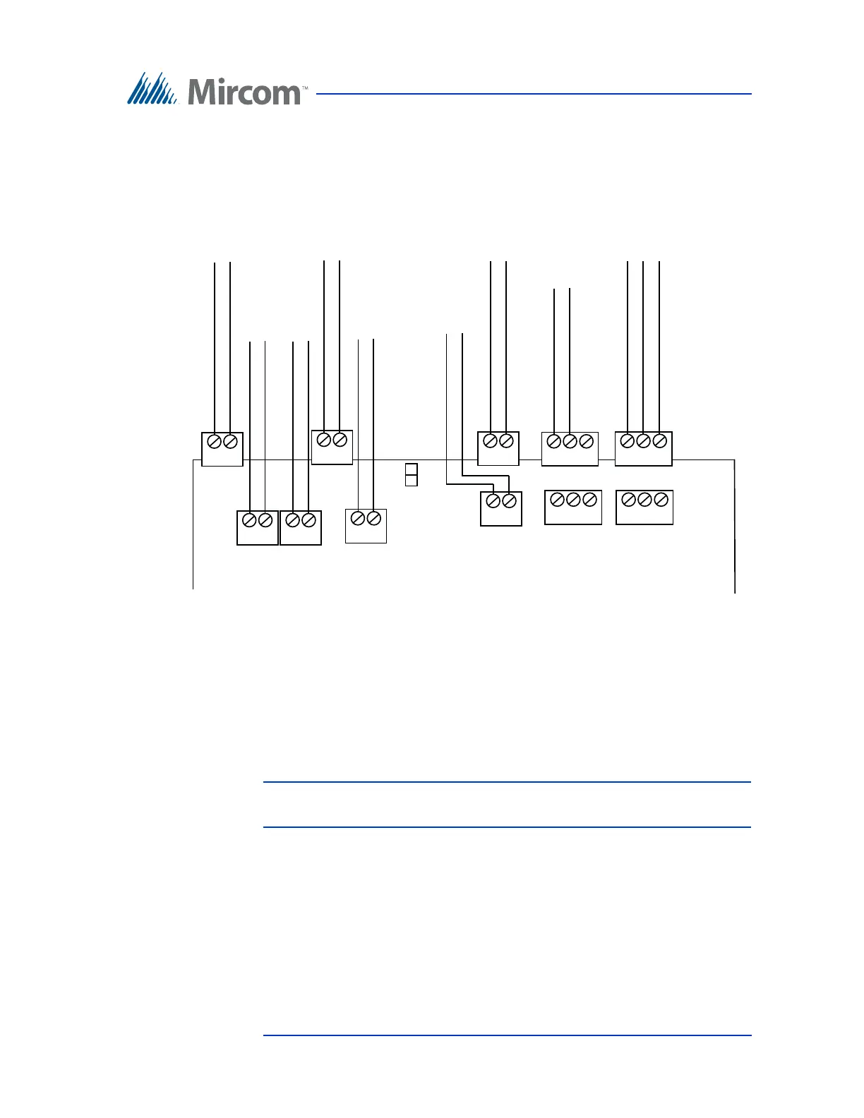
Figure 31 shows the connectors at the top of the controller board.
Figure 31. Controller Board Connectors - Top
4.3.1 Telephone Lines 1 to 5
The telephone lines are situated at the top left of the main controller board.
Both NSL and ADC lines can be connected. Each T/R line is polarity insensitive
and can be reversed.
Note: Non-configurable PBX systems are not supported. For more
information, contact technical support at Mircom.
4.3.2 JW8
JW8 must be set to define the operating state of the door strike relay as normally
open or normally closed. Use the jumper wire to connect to either the normally
open (position 2 - top) or the normally closed pin (position 1 - bottom). For
example, when using a maglock, connect the jumper wire to the normally closed
pin (position 1).
Telephone Lines 1 to 5
Line 1
T R
Line 2
T R
Line 3
T R
Line 5
T R
Line 4
T R
AC
Door Strike
AC or DC
Input Door
Strike Supply
DC Output 1
Door Strike
Aux. Door
Output 2
Relay
General Relay
Output 4
NO NC C
NO NC C
General Relay
Output 3
JW8