NSL Relay Cabinet Installation and Wiring
Version 3.7 Telephone Access System Installation and Operation Manual 71 (119)
LT-969 Copyright January 2017
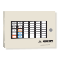
Figure 38 shows a TX3-NSL-8M Relay Control Unit.
Figure 38. TX3-NSL-8M Relay Control Unit
5.2.2 2012 NSL Relay
The NSL Backplane board contains up to eight 2012 NSL Relay Boards. Each
2012 NSL Relay Board has 12 relays, allowing for a total of 96 relays.
5.2.3 NSL Expanders
NSL expanders plug into the NSL Backplane Board connectors and consist of:
• TX3-8EC NSL Eight Relay Card Backplane Expander
• TX3-16EC NSL 16 Relay Card Backplane Expander
Extension cables provide connections between adjacent enclosures using the
expansion connectors. See Section 5.3 for a description of the NSL Backplane
Board connectors.
The TX3-8EC NSL Eight Relay Backplane Expander and the TX3-16EC
NSL 16 Relay Backplane Expander are housed in their own cabinet and can be
connected with two cables to provide an additional capacity for 8 or 16 relay
boards respectively.
TX3-NSL-8M Relay Control Unit
NSL Main Controller
NSL Backplane Board
 Loading...


