80 (119) Telephone Access System Installation and Operation Manual Version 3.7
LT-969 Copyright January 2017
NSL Relay Cabinet Installation and Wiring
5.3.10 Setting the Backplane Number
Relay addresses are numbered to show the relay card’s connector location and
backplane number setting. Table 4 provides sample addresses for the first three
backplane number jumper settings.
For example, when the backplane number jumper setting is set to 1, the first relay
on P3 relay board has an address of 1. When the backplane number setting is set
to 2, the first relay on P3 relay board has an address of 97.
To set the backplane number
1. Determine the relay address according to the relay card’s connector
location and backplane number setting.
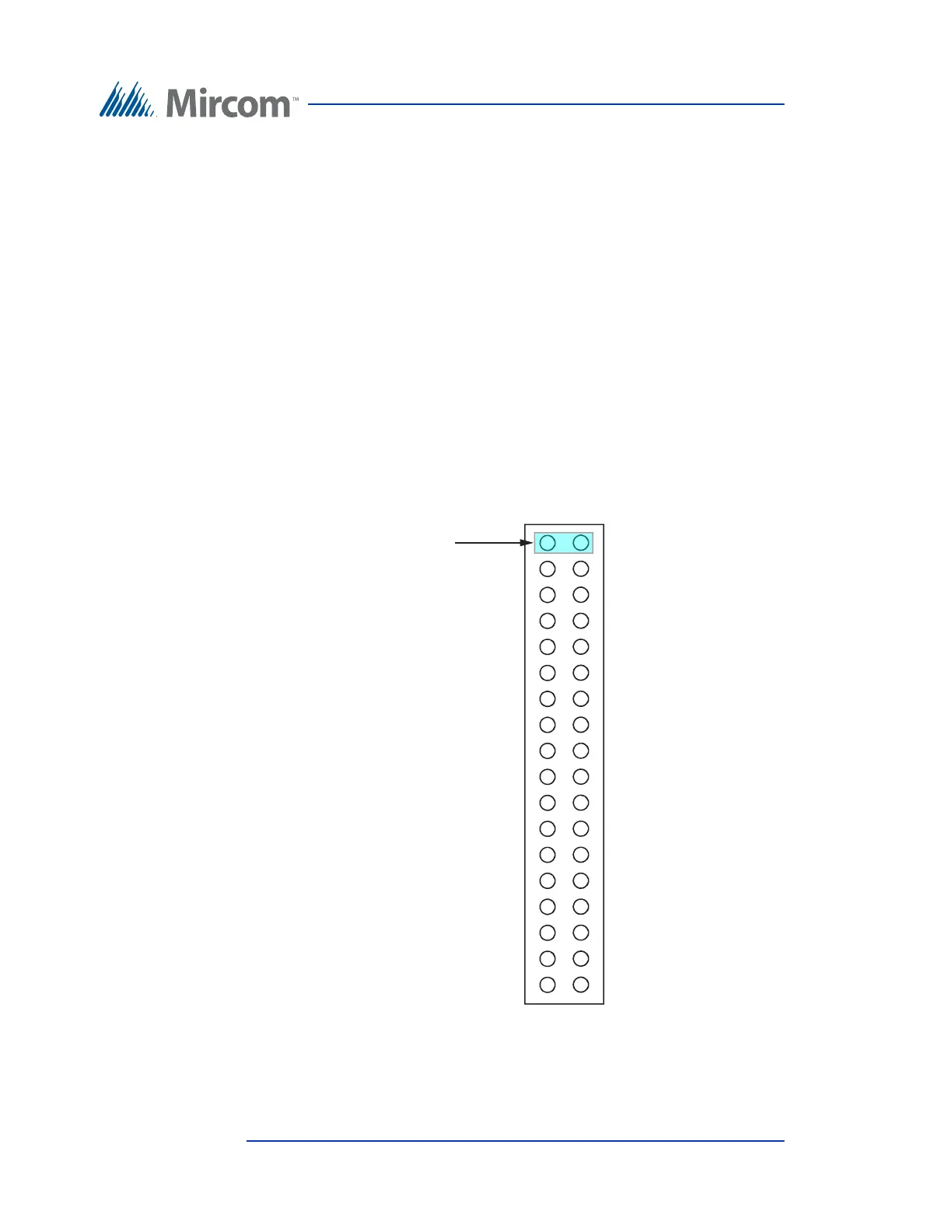
2. Using a jumper, set the backplane number across the Backplane Number
Selection pins as shown in Figure 45.
Figure 45. Backplane Number Section
1
2
3
4
5
6
7
8
9
10
11
12
13
14
15
16
Jumper Setting
Backplane Number
Selection