Enclosure Installation
Version 3.7 Telephone Access System Installation and Operation Manual 33 (119)
LT-969 Copyright January 2017
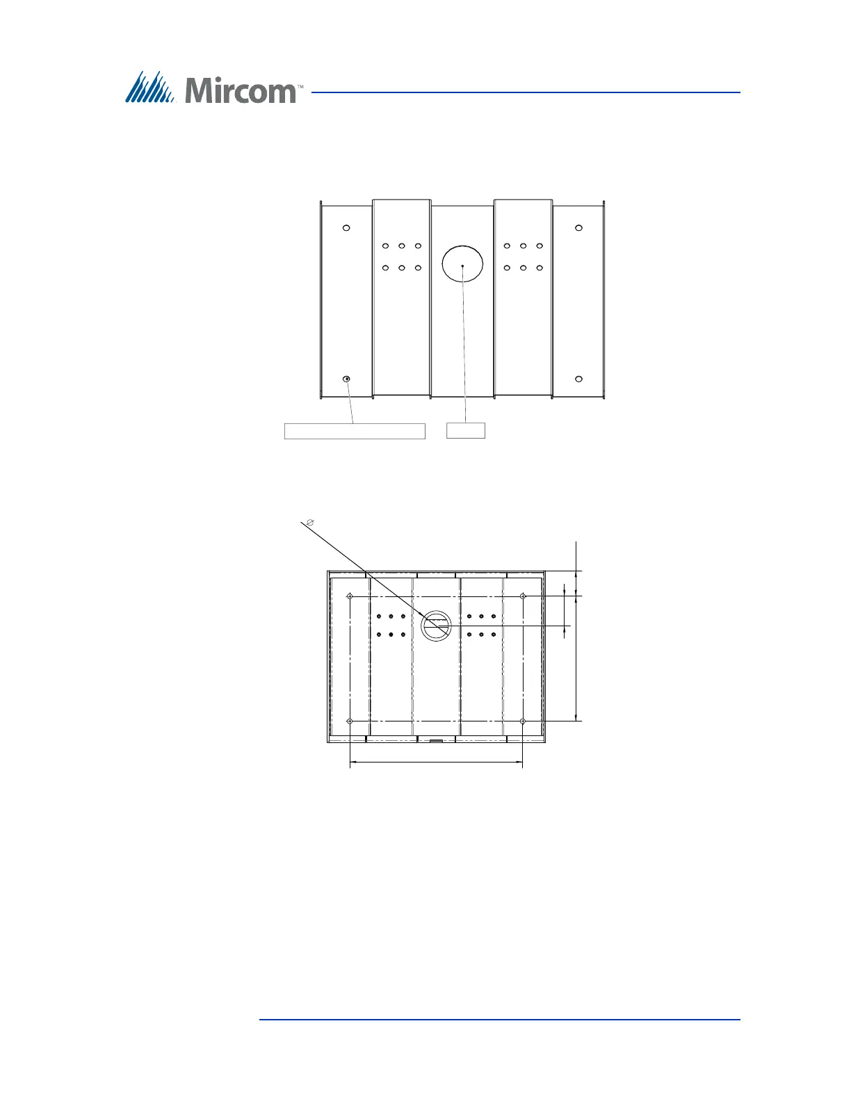
6. Using the Kiosk base plate as a template, trace an opening in the floor for
the cutout and mark the 4 base plate mounting hole locations as shown in
Figure 10. Ensure that the base plate is aligned with the electrical conduit.
Figure 10 Base Plate Mounting Holes
Figure 11 shows the dimensions of the base plate.
Figure 11 Base Plate Dimensions (inches)
7. Cut an opening in the floor for the electrical and communication cables.
8. Run the wires through the base plate opening.
9. Secure the base plate to the floor using 4 bolts in the base plate mounting
holes shown in Figure 10. The holes are 0.406” in diameter.
Cutout
Base plate mounting holes (x4)
10.300
14.244
2.500
2.450
2.107