70 (119) Telephone Access System Installation and Operation Manual Version 3.7
LT-969 Copyright January 2017
NSL Relay Cabinet Installation and Wiring
The top two mounting holes are 6 3/16 inches apart.
To mount the NSL Relay Cabinet
1. Using the back cover as a template mark the top two mounting hole
locations 6 3/16 inches apart as shown in Figure 37.
2. Place the screws halfway into the wall in the position shown using a
suitable screw.
3. Hang the box onto the two screws.
4. Screw the other two screws at the bottom of the panel.
5. Tighten all four screws into place.
5.2 NSL Relay Control Unit and Expanders
The TX3-NSL-8M NSL Relay Control Unit, TX3-8EC and TX3-16EC NSL
Relay Backplane Expanders perform the following functions:
• Telephone switching functionality to facilitate voice communication
between the resident's phone and the lobby
• Generating call waiting tones to the resident if the line is busy.
• Provide access control by the resident using the telephone keypad.
• Low power operation from one 16V AC transformer.
5.2.1 TX3-NSL-8M NSL Control Unit
The TX3-NSL-8M Relay Control Unit consists of:
• NSL Main Controller Board
• NSL Backplane Board
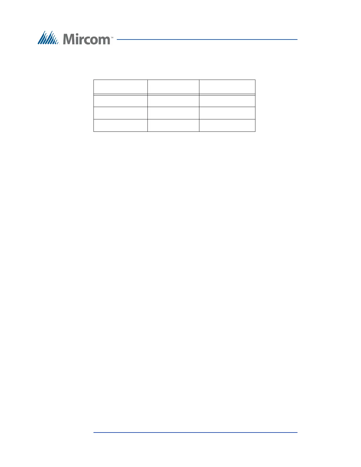
Table 3: NSL Relay Cabinet Dimensions
Model Number Dim ‘A’ Dim ‘B’
TX3-8EC 10 1/8” 13 15/16”
TX3-NSL-8M 23 3/16” 27”
TX3-16EC 23 3/16” 27”